
Optical communication apparatus and optical communication method

a communication apparatus and optical communication technology, applied in the direction of electrical apparatus, electromagnetic transmission, close-range type systems, etc., to achieve the effect of effective optical communication

Inactive Publication Date: 2012-03-20
SONY CORP
View PDF19 Cites 40 Cited by
  • Summary
  • Abstract
  • Description
  • Claims
  • Application Information

AI Technical Summary

Benefits of technology

The present invention provides an optical communication apparatus and method for effectively communicating when a user watches another person or an object. The apparatus includes a light transmission section, a light reception section, and a control section. The control section determines whether the other optical communication apparatus is an information communication target and causes the light transmission section to transmit communication request information and own identification information to the other optical communication apparatus. The light reception section receives the communication request information and the identification information from the other optical communication apparatus and causes the display section to display an indication based on the information transmitted. The apparatus can also capture the visual line direction of the user and display the indication based on the captured information. The technical effect of the invention is to provide an optical communication apparatus and method that can effectively communicate when a user watches another person or an object.

Problems solved by technology

Although optical communications have been used in various fields, techniques of information communications effective in the state of which persons face each other (they watch each other) and a technique of obtaining information in the state of which a person faces an object (he or she watches the object) have not yet proposed.

Method used


Image

  • Optical communication apparatus and optical communication method
  • Optical communication apparatus and optical communication method
  • Optical communication apparatus and optical communication method

Examples


Embodiment Construction

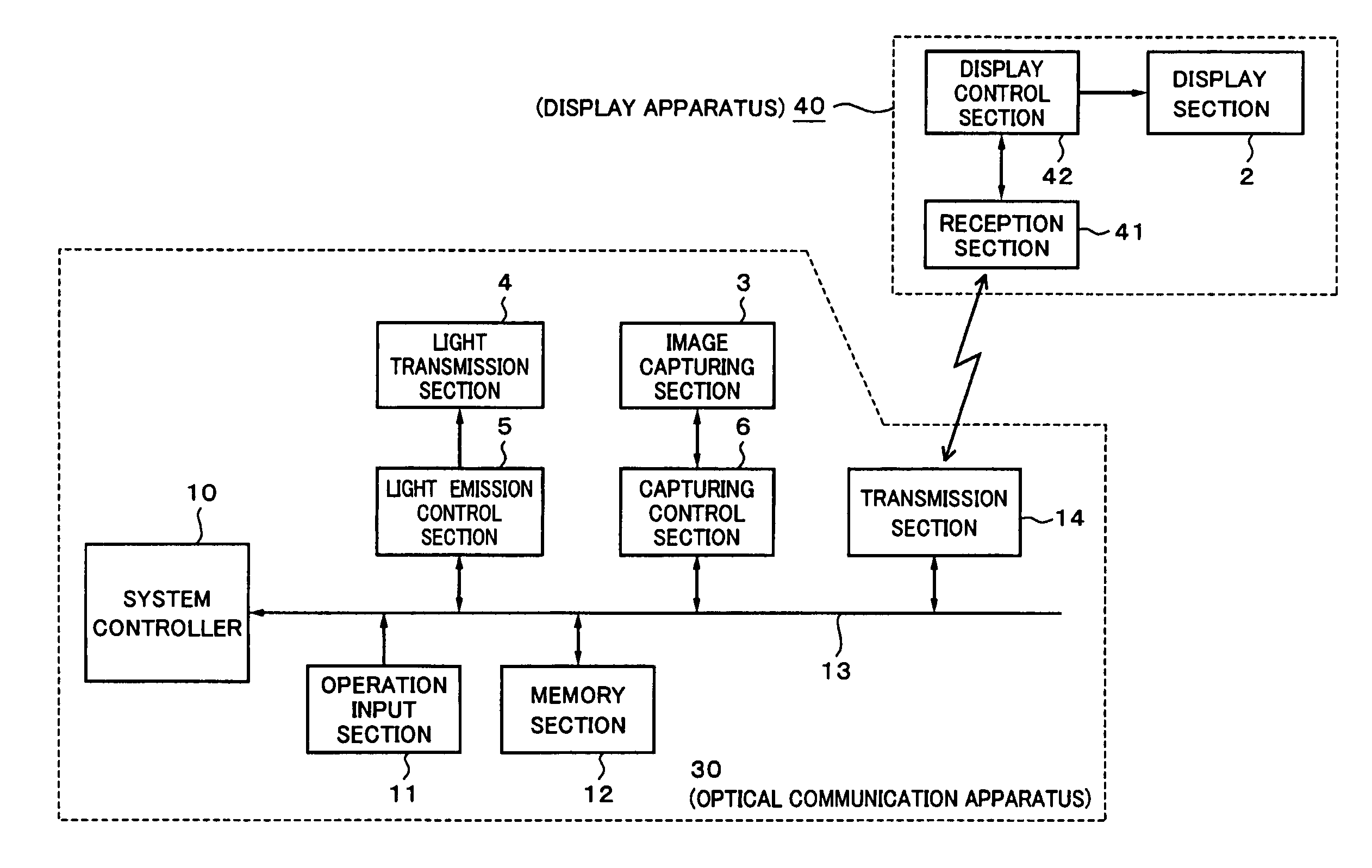
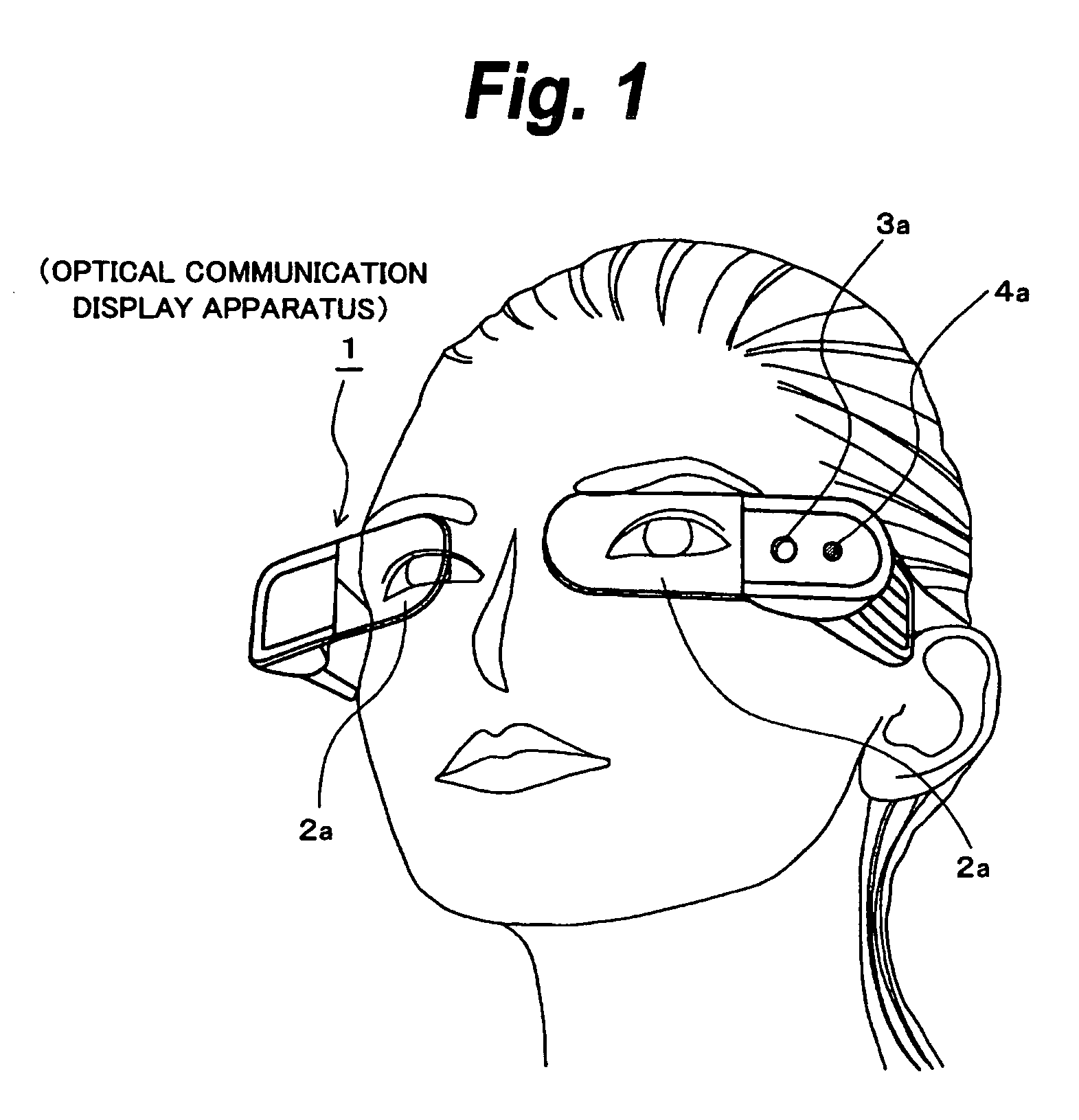
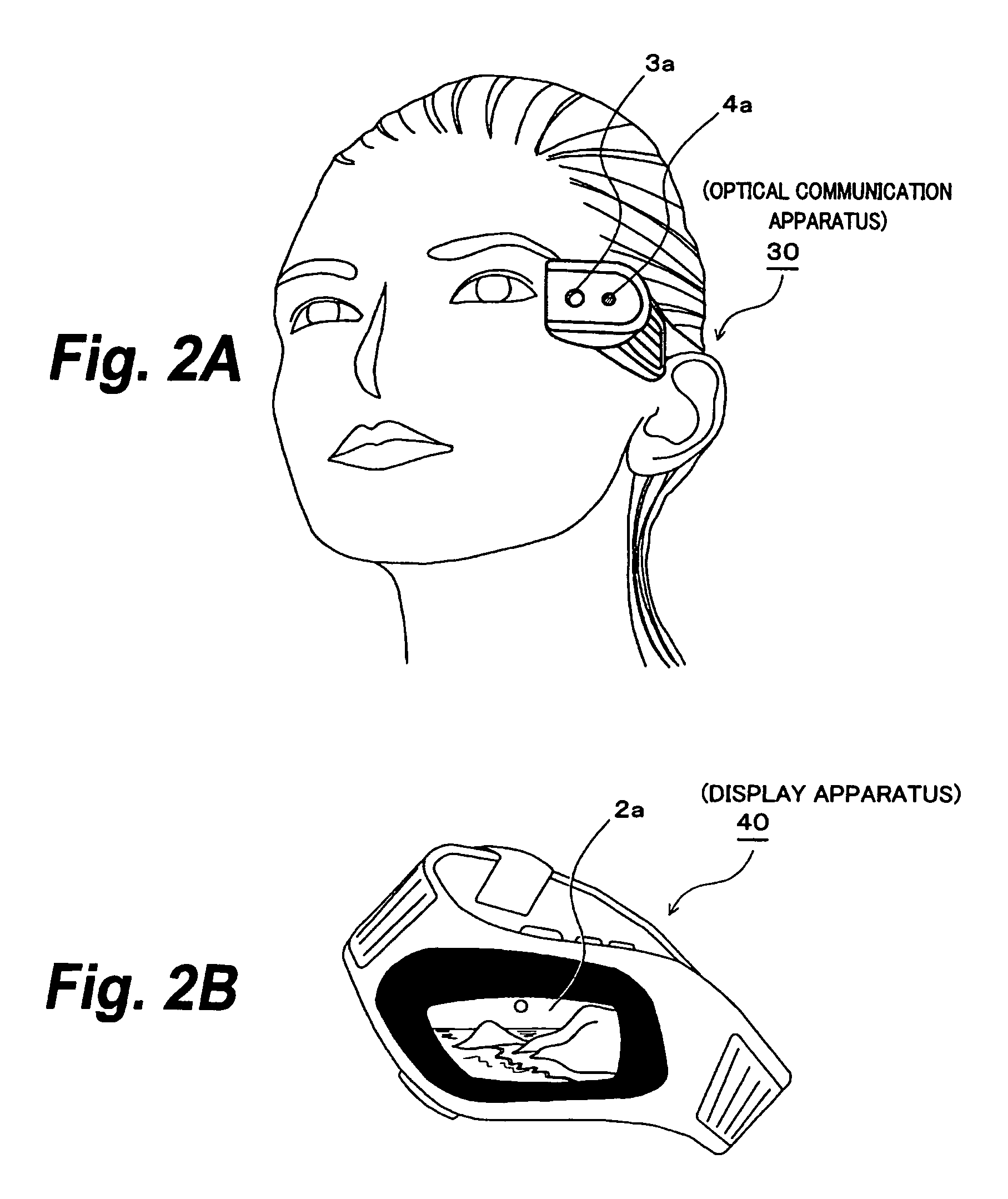
[0061]Next, an optical communication apparatus and a communication method according to embodiments of the present invention will be described. In these embodiments, an optical communication display apparatus 1 and an optical communication apparatus 30 that a user wears, and an optical communication apparatus 50 mounted on an apparatus-mounted object other than a person correspond to an optical communication apparatus as set in claims of the present application. In addition, as processes of the optical communication display apparatus 1, the optical communication apparatus 30, and the optical communication apparatus 50, optical communication methods of embodiments of the present invention are performed. In addition, the optical communication display apparatus 1, the optical communication apparatus 30, and the optical communication apparatus 50 may be another optical communication apparatus as set forth in claims of the present application.

Embodiments of the present invention will be d...


PUM


Abstract

An optical communication apparatus is disclosed. The optical communication apparatus includes a light transmission section, a light reception section, and a control section. The light transmission section causes a light emitting portion which outputs light in a visual line direction of a user to transmit information. The light reception section causes a light receiving portion which receives light from the visual line direction of the user to receive information. The control section determines whether or not another optical communication apparatus is an information communication target based on identification information when the light reception section has optically received communication request information and the identification information from the other optical communication apparatus and causes the light transmission section to optically transmit communication response information to the other optical communication apparatus when the control section has determined that the other optical communication apparatus be the information communication target.

Description

CROSS REFERENCES TO RELATED APPLICATIONS[0001]The present invention contains subject matter related to Japanese Patent Application No. 2007-010273 filed on Jan. 19, 2007 and Japanese Patent Application No. 2007-113964 filed on Apr. 24, 2007, the entire contents of which being incorporated herein by reference.BACKGROUND OF THE INVENTION[0002]1. Field of the Invention[0003]The present invention relates to an optical communication apparatus and an optical communication method, in particular, to a technique of mutual communications between optical communication apparatus so as to exchange information therebetween.[0004]2. Description of the Related Art[0005]Japanese Patent Application Laid-Open No. 2004-56343, referred to as Patent Document 1, discloses a technique of communicating information with a light blinking pattern of a light emitting device such as an LED (Light Emitting Diode). Japanese Patent Application Laid-Open No. HEI 4-26289, referred to as Patent Document 2, discloses a...

Claims


Application Information

Patent Timeline
Patent Type & Authority Patents(United States)
IPC IPC(8): H04B10/00H04B10/11H04B10/116
CPCH04B10/1143
Inventor ASUKAI, MASAMICHIEBISAWA, KANSAKO, YOICHIROTSURUTA, MASAAKIITO, TAIJI
Owner SONY CORP
Learn More