Sluice system for a vacuum facility

a vacuum coating and sluice system technology, applied in the direction of machines/engines, liquid transferring devices, positive displacement liquid engines, etc., to achieve the effect of reducing construction and system technology, reducing the total cycle time of the sluice system, and reducing the cost of construction and system technology

Inactive Publication Date: 2012-03-20
VON ARDENNE ANLAGENTECHNIK GMBH
View PDF19 Cites 1 Cited by
  • Summary
  • Abstract
  • Description
  • Claims
  • Application Information

AI Technical Summary

Benefits of technology

[0007]The task of the invention involves designing the sluice system of the vacuum coating facility in such a way that the total cycle time of the sluice system is reduced while, at the same time, the constructional and system technology and expense is reduced.
[0009]The omission of the entire fine vacuum sluice chamber also does away with the need for its sluice valves, which leads to a saving of the valve opening and closing times of the fine vacuum sluice chamber and reduces the idle times of the substrate. The total cycle time of the sluice system is therefore advantageously reduced. At the same time, there is no longer a need for structural space for the fine vacuum sluice chamber on both sides of the vacuum coating chamber.Pump System

Problems solved by technology

2·10−3 bar, and at a higher pressure the excessively high gas components in the pumping medium led to faults owing to significant friction and heat formation.

Method used


Image

  • Sluice system for a vacuum facility
  • Sluice system for a vacuum facility
  • Sluice system for a vacuum facility

Examples


Embodiment Construction

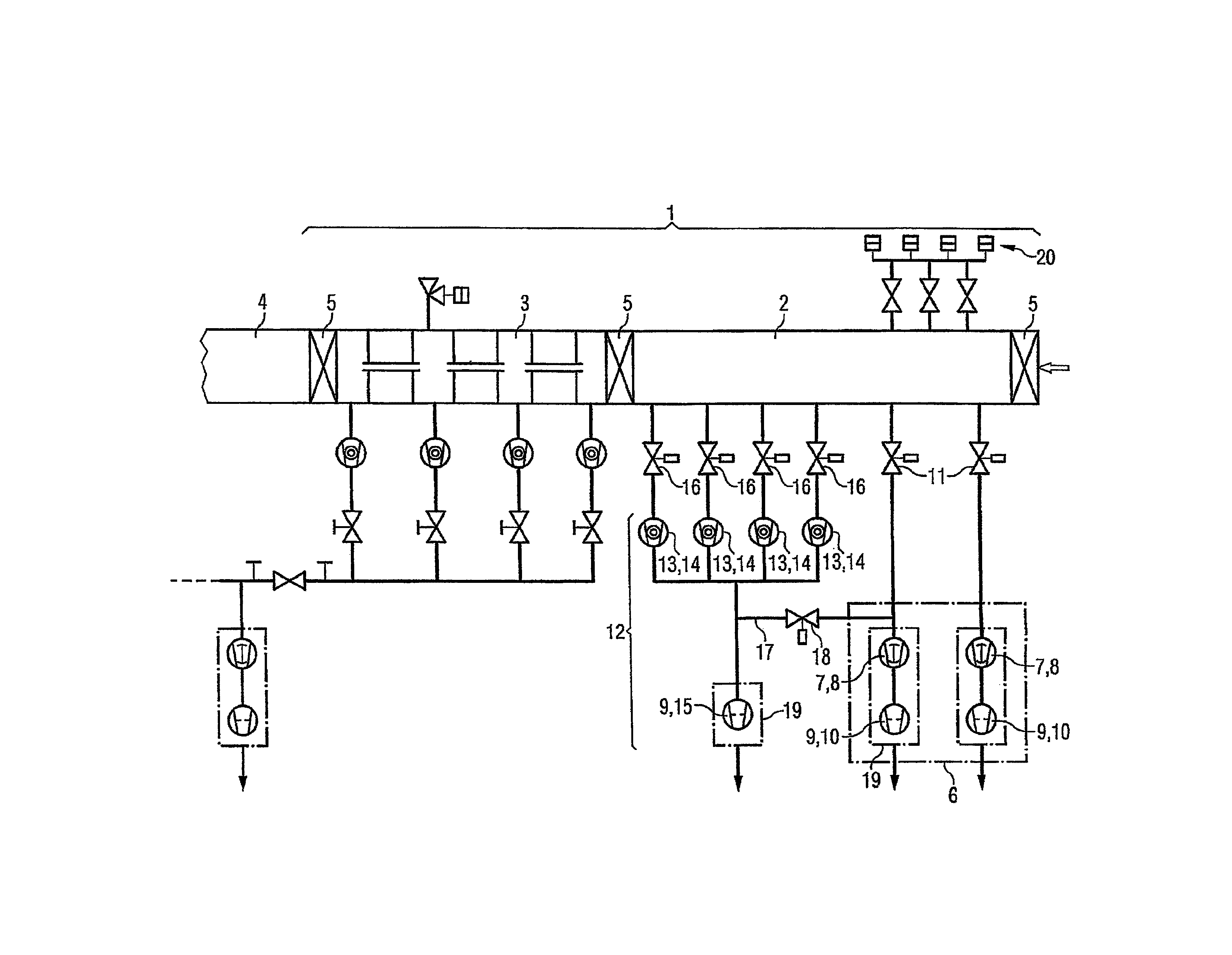
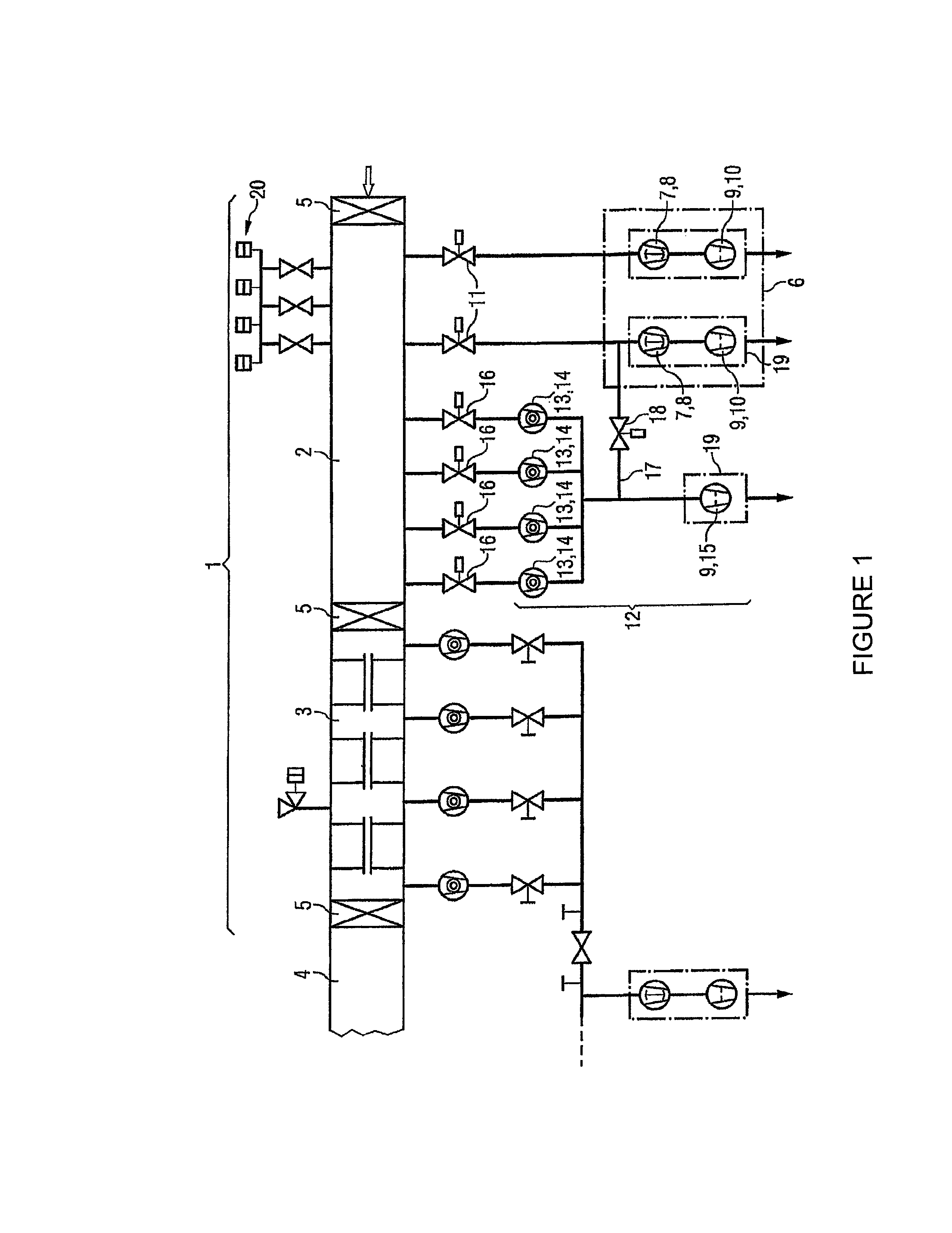
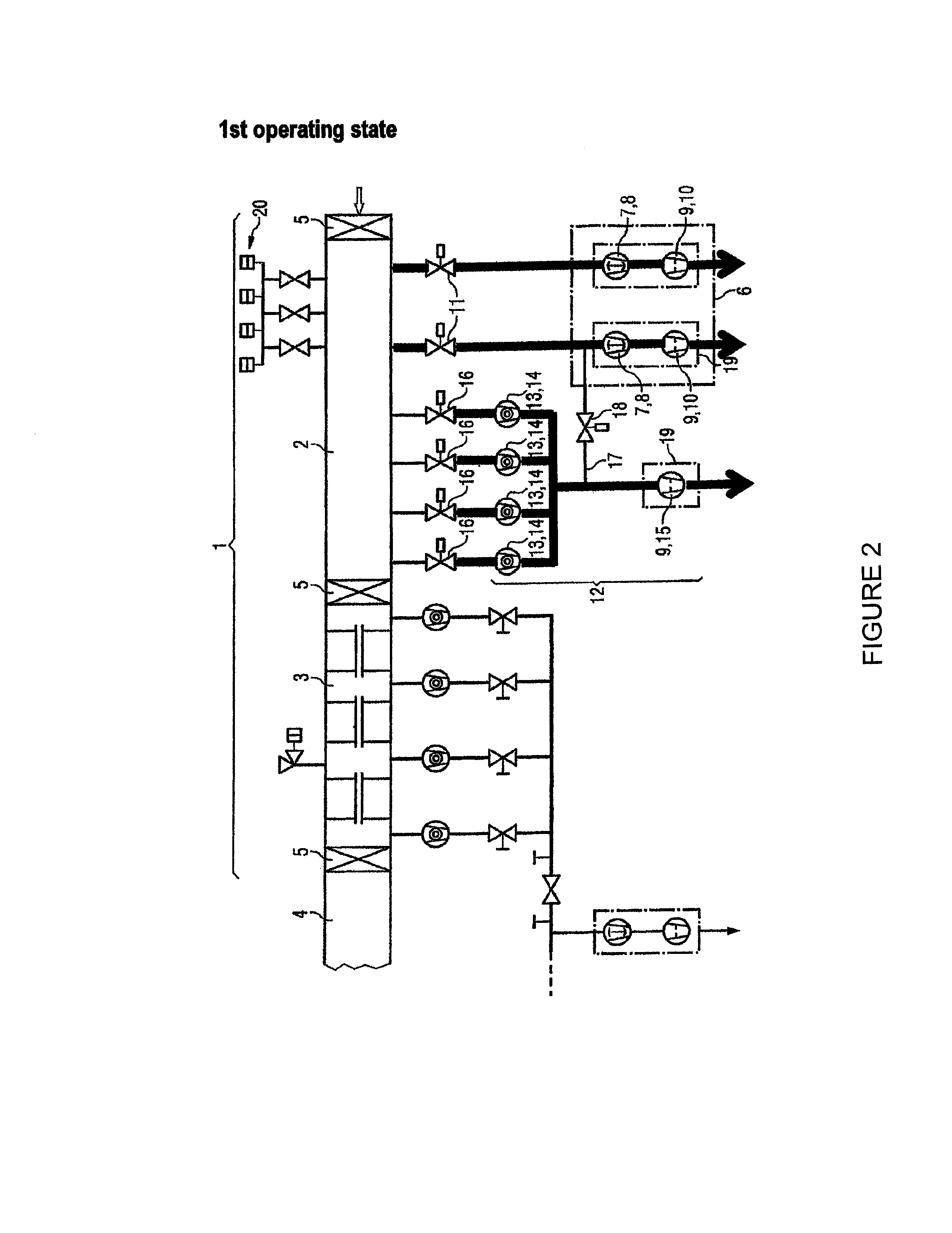
[0016]The invention will be explained by means of an embodiment example. The sluice system 1 on the input side for in-line coating facilities is shown in the accompanying drawing. Only the components relevant for the invention are shown. In the sluice system 1 according to the invention, the transfer chamber 3 is connected to the prevacuum sluice chamber 2, which in turn directly adjoins the coating chamber 4. The individual chambers are separated from each other via vacuum system sluice valves 5. The prevacuum is generated in the prevacuum sluice chamber 2 by prevacuum pump systems 6 connected in parallel to the prevacuum sluice chamber. These pump systems respectively consist of a Roots pump 7 as a main pump 8 and a rotary slide-valve pump 9 connected in series as a backing pump. Both connections of the prevacuum pump system 6 can be separated from the prevacuum sluice chamber 2 via regulating valves 11. A fine vacuum pump system 12 with four turbo-molecular pumps 13 as main pumps...


PUM

PropertyMeasurementUnit
vacuum pressureaaaaaaaaaa
pressureaaaaaaaaaa
vacuumaaaaaaaaaa

Abstract

A sluice system for a vacuum coating facility for coating substrates that can be moved through the vacuum coating in a direction of conveyance comprises a prevacuum slice chamber and a transfer chamber adjoining a coating chamber, wherein a fine vacuum can be regulated before the transfer chamber on the input side in the direction of conveyance and after the transfer device on the output side in the direction of conveyance. The prevacuum sluice chamber is directly adjacent to the transfer chamber and the fine vacuum can be regulated in the prevacuum sluice chamber. A high-vacuum pump system can also alternatively and selectively be connected to the prevacuum sluice chamber.

Description

CROSS-REFERENCE TO RELATED APPLICATIONS[0001]This application is a continuation of U.S. application Ser. No. 10 / 574,368, filed Mar. 31, 2006 now abandoned which is a 35 USC Section 371 filing of International application PCT / DE2004 / 002265 filed on Oct. 12, 2004 and published in German as WO 2005 / 040452 on May 6, 2005, and claims priority from German patent application number 103 48 639.9 filed on Oct. 15, 2003, the full contents of these applications being hereby incorporated herein by reference.BACKGROUND ART[0002]The invention relates to a sluice system for a vacuum coating facility for coating substrates that can be moved through the vacuum coating facility in a direction of conveyance. On the input and output sides, the sluice system comprises a prevacuum sluice chamber and a transfer chamber adjoining a coating chamber, wherein a fine vacuum can be regulated before the transfer chamber on the input side in the direction of conveyance and after the transfer device on the output ...

Claims


Application Information

Patent Timeline
Patent Type & Authority Patents(United States)
IPC IPC(8): E03B5/00C23C14/56
CPCC23C14/566Y10T137/86131
Inventor GAWER, OLAFMELCHER, JENSSCHULZE, DIETMARHECHT, HANS-CHRISTIAN
Owner VON ARDENNE ANLAGENTECHNIK GMBH
Why Eureka
Try Eureka