
Closed-loop efficiency modulation for use in AC powered applications

a technology of efficiency modulation and closed-loop efficiency, which is applied in the direction of dc-dc conversion, dc-dc conversion, and conversion with intermediate conversion to dc, etc., can solve the problems of not optimizing the overall power efficiency of the whole system, the input and output voltage the operating set points of the first and second converters, etc., to achieve the effect of maximizing power efficiency

Active Publication Date: 2012-03-13
WSOU INVESTMENTS LLC
View PDF4 Cites 35 Cited by
  • Summary
  • Abstract
  • Description
  • Claims
  • Application Information

AI Technical Summary

Benefits of technology

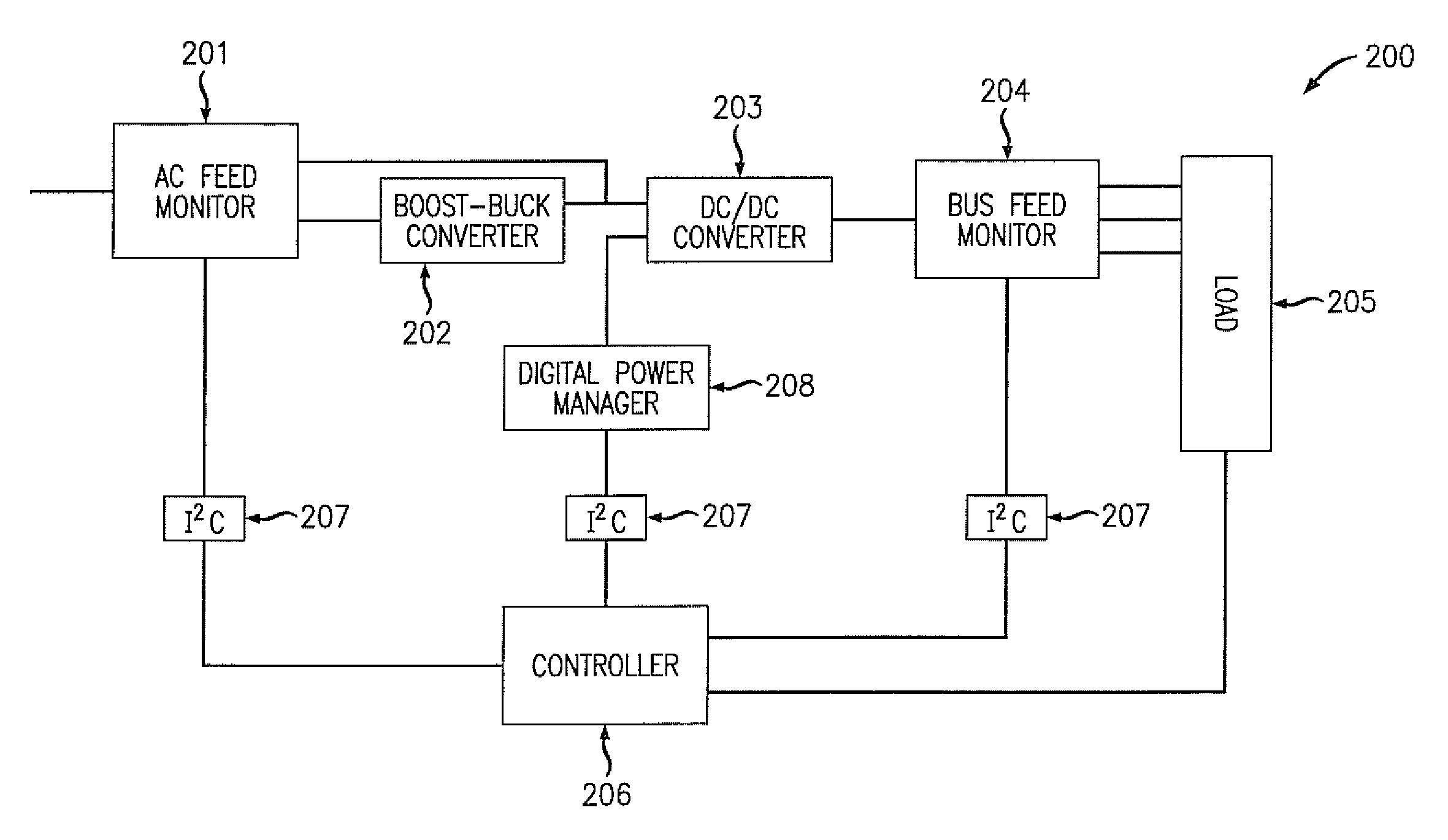
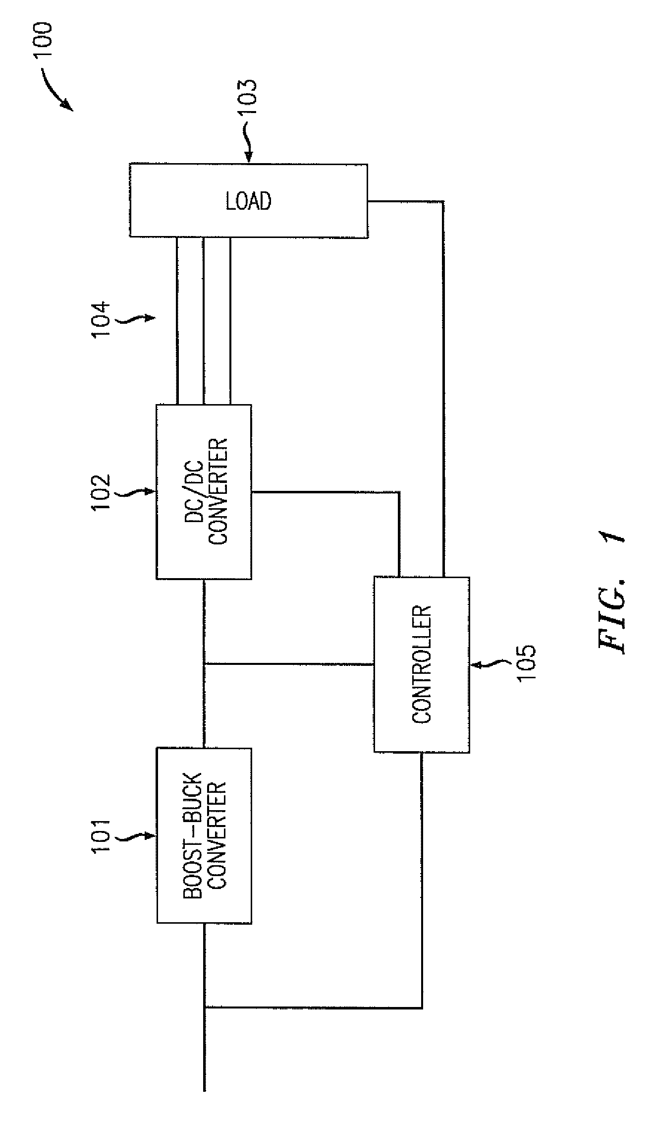
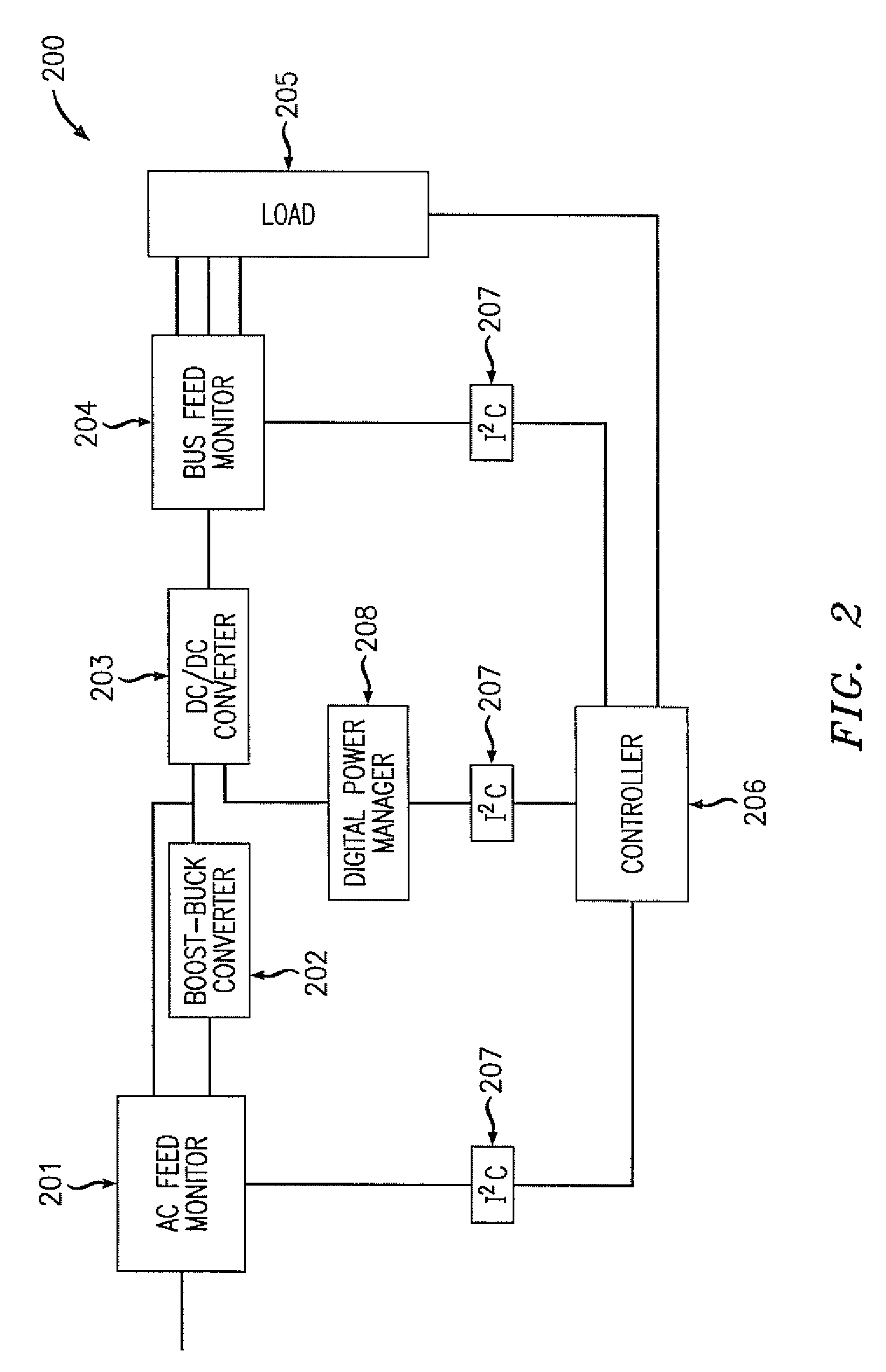
"The patent describes a system for efficiently converting AC to DC power. It uses a series of DC / DC converters that are controlled by a controller to maximize power efficiency. The controller monitors the input and output of the converters and adjusts their outputs accordingly. The system also includes sensors to monitor the input and output of the converters and a series of trim voltage providers to adjust the feedback inputs of the converters. The technical effects of this system include improved efficiency and power conversion."

Problems solved by technology

However, a boost converter only creates a higher-voltage regulated DC output, which also requires another switch-mode converter in series with the boost converter to produce the desired output voltage from the DC bus for use with other devices.
This topology may increase power factor, but it does not optimize the overall power efficiency of the whole system, as it does not address the system architecture or component losses.
For example, the operating set points, the input and output voltages of the first and second converters, may not be optimized with each other to minimize power dissipation within the whole system.
For a given output power, current and voltage are inversely proportional, so that minimizing one power loss may create an unacceptable value for other power losses.

Method used


Image

  • Closed-loop efficiency modulation for use in AC powered applications
  • Closed-loop efficiency modulation for use in AC powered applications
  • Closed-loop efficiency modulation for use in AC powered applications

Examples


Embodiment Construction

[0023]The foregoing objects and advantages of the invention are illustrative of those that can be achieved by the various exemplary embodiments and are not intended to be exhaustive or limiting of the possible advantages that can be realized. Thus, these and other objects and advantages of the various exemplary embodiments will be apparent from the description herein or can be learned from practicing the various exemplary embodiments, both as embodied herein or as modified in view of any variation that may be apparent to those skilled in the art. Accordingly, the present invention resides in the novel methods, arrangements, combinations, and improvements herein shown and described in various exemplary embodiments.

[0024]According to the exemplary embodiments, an AC-to-DC power converter contains, in addition to an AC-to-DC rectifying means, a first DC / DC active Power Factor Correction (PFC) converter and a second DC / DC converter. As with any conversion circuitry, both converters diss...


PUM


Abstract

A system and method for closed-loop efficiency modulation for an AC / DC power system is provided. A boost-buck converter and a DC / DC converter connected in series receive a rectified DC feed signal from a AC input signal and deliver a modified DC output to an active load. A controller receives power data at various stages of the system and uses that data to modify a series of trim voltages provided to the feedback inputs of the respective converters to modify each converters output voltage. The controller modifies each converter's output voltage to maximize power efficiency while monitoring other data in the system to ensure the system is operating correctly and safely.

Description

BACKGROUND[0001]1. Technical Field[0002]The embodiments relate generally to power efficiency in power supply systems.[0003]2. Description of Related Art[0004]Engineers have historically used DC power supplies to act as a buffer between the equipment requiring electrical power and the primary electric power source. In the United States and many other nations, electric power is usually transmitted using AC power, which, in turn, requires some form of an AC / DC converter to convert the delivered AC power to a form that the equipment can properly use. Switching-mode DC power supplies convert AC voltage to DC voltage using components with low losses in power dissipation, such as capacitors, inductors, transformers, and switches (transistors, diodes etc).[0005]The efficiency of a switching mode power supply (SMPS) varies depending on the load. For example, a SMPS operates at a much higher efficiency when fully loaded than at low loads. There are three main areas where one can increase effi...

Claims


Application Information

Patent Timeline
Patent Type & Authority Patents(United States)
IPC IPC(8): H02M5/42
CPCH02J1/00H02M7/217H02M3/158H02M2001/007H02M1/007
Inventor WHITTAM, SIMON PGRYBA, JOHN S.PARRELL, MICHAEL W.
Owner WSOU INVESTMENTS LLC
Learn More