
Lock device for a vehicle

a technology for locking devices and vehicles, applied in anti-theft devices, lock applications, movable seats, etc., can solve problems such as generating chattering nois

Inactive Publication Date: 2012-03-06
AISIN SEIKI KK
View PDF10 Cites 26 Cited by
  • Summary
  • Abstract
  • Description
  • Claims
  • Application Information

AI Technical Summary

Benefits of technology

The present invention is a lock device for a vehicle that includes a base plate, latch, pawl, rotation lever, thrust plate, and biasing means. The latch is pivotally supported on the base plate and can engage or disengage with a striker fixed to the other member. The pawl is rotationally supported on the base plate and can keep the latch in a releasable position or prevent it from returning to the lock release position. The thrust plate has an inclined cam surface that can secure the striker between it and the latch. The biasing means can bias the latch and pawl in the same direction or in opposite directions. The technical effect of this invention is to provide a reliable and secure lock device for vehicles that can prevent unauthorized access and ensure safety.

Problems solved by technology

The loosened engagement may lead to a generation of chattering noise.

Method used


Image

  • Lock device for a vehicle
  • Lock device for a vehicle
  • Lock device for a vehicle

Examples


Embodiment Construction

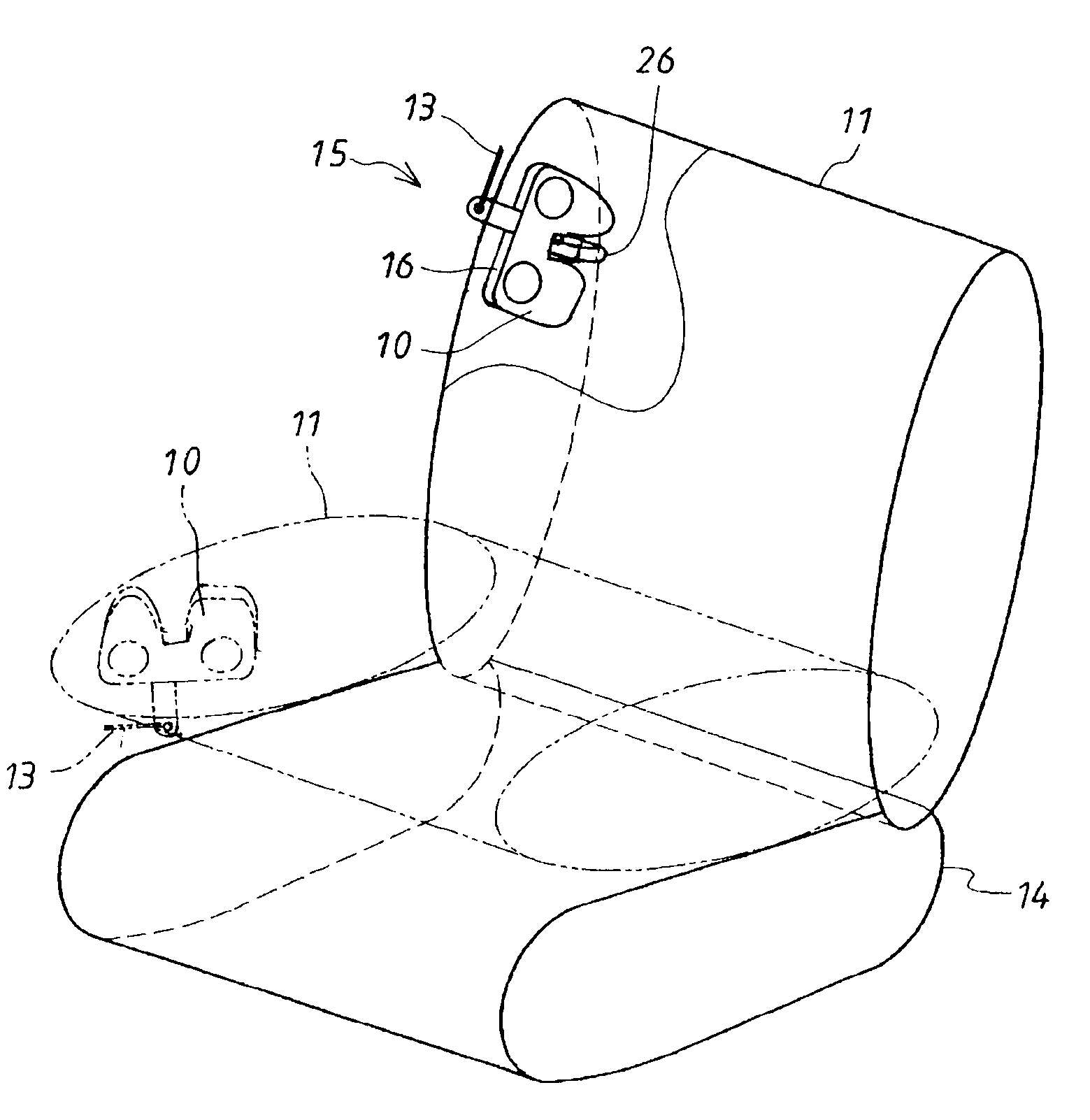
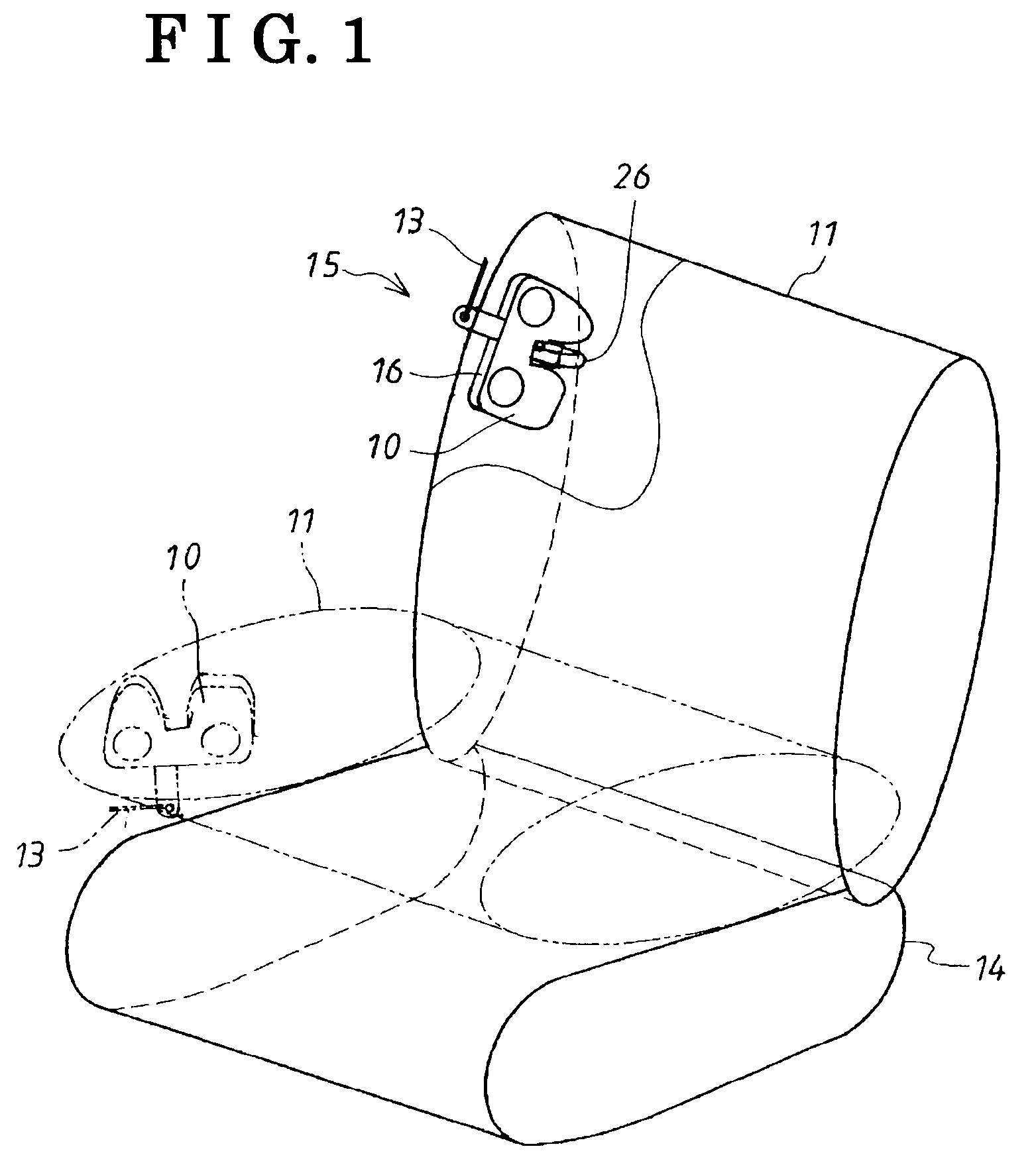
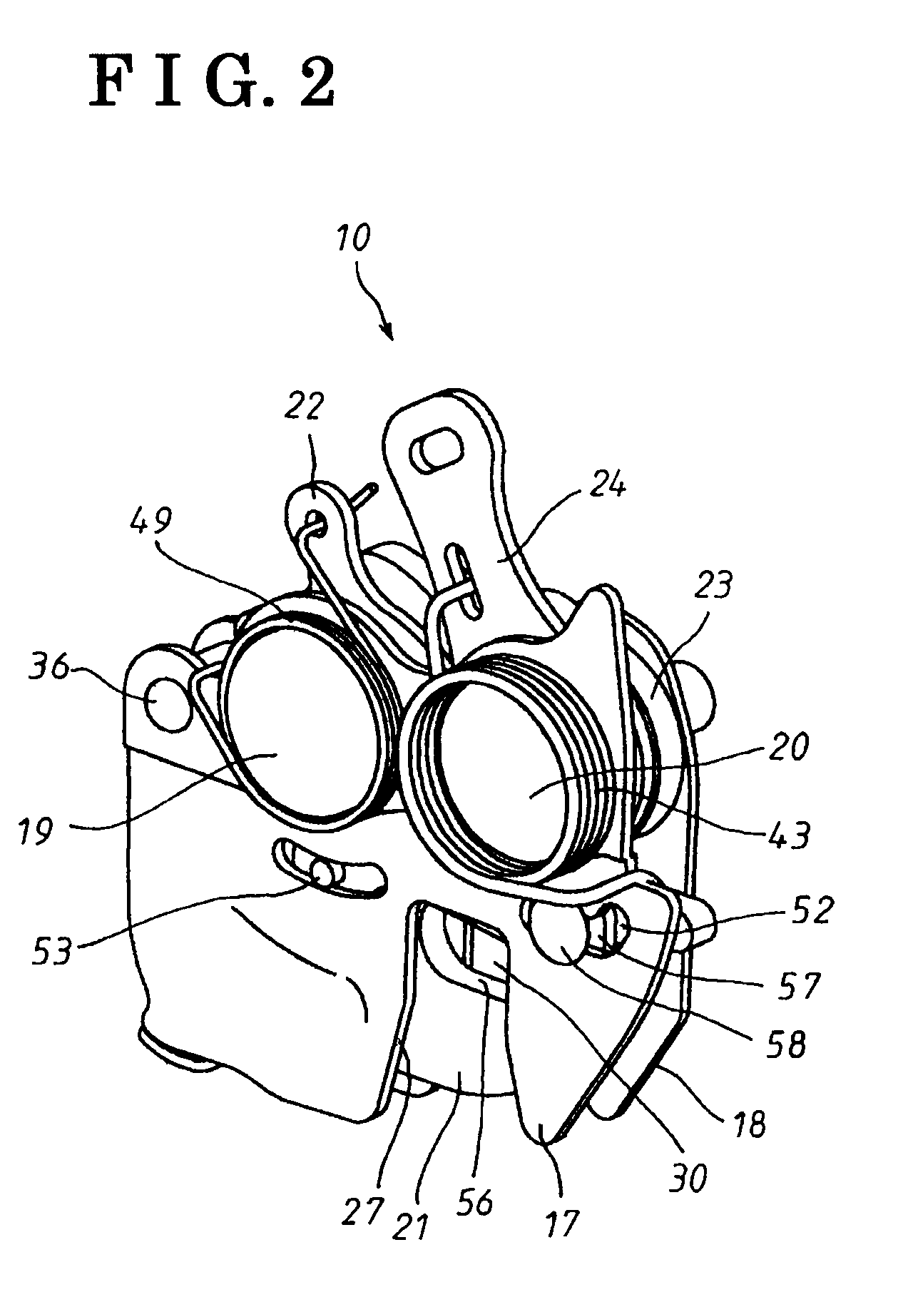
[0020]The detail of the lock device used in a vehicle according to the invention will be explained herein after with the attached drawings. As shown in FIG. 1, a lock device 10 is fixed to a side frame of a seat back 12 (movable member) of a rear seat 11 through a base plate 16. The seat back 12 is movable relative to a seat cushion 14 of the seat 11. A striker 26 is fixed to an inner side of a vehicle body (fixed member). The striker 26 engages with the lock device 10 when the seat back 12 is moved upright. The striker and the lock device 10 form a vehicle lock device 15. The vehicle lock device 15 is locked when the lock device 10 engages with the striker 26 under the seat back being in an upright position. The locked position is released by operating an operation lever 13 attached to the lock device 10 for allowing the seat back to be forwardly inclined (folded) relative to the seat cushion 14 of the seat 11. The inclined or folded position of the seat back 12 is shown in FIG. 1 ...


PUM


Abstract

A lock device for a vehicle includes a base plate provided with an entrance / retracting groove for receiving or retracting a striker and a latch pivotally supported on the base plate by a latch axis. The latch includes a lock groove engaging with or disengaging from the striker entering the entrance / retracting groove and rotatable between a lock release position allowing the striker entering into the entrance / retracting groove and a lock position for holding the striker in the entrance / retracting groove by the movement of the striker. A first biasing member is provided for biasing the latch in the rotational direction to the release position to bias the pawl in a rotational direction towards the release preventing position and a second biasing member is provided for biasing the rotation plate in a rotational direction towards the release position of the latch.

Description

CROSS REFERENCE TO RELATED APPLICATIONS[0001]This application is based on and claims priority under 35 U.S.C. §119 to Japanese Patent Application 2007-317009, filed on Dec. 7, 2007, the entire contents of which is incorporated herein by reference.FIELD OF THE INVENTION[0002]The present invention relates to a lock device for a vehicle, and more particularly, to a seat lock device used for locking a vehicle seat to a vehicle fixed portion such as a vehicle floor, a door lock device used for locking a vehicle door to a vehicle body, or a lid lock device used for locking an engine hood rid, a luggage room (trunk room) cover rid or a fuel tank rid to an appropriate portion of the vehicle body.BACKGROUND[0003]In an automobile, in order to widely use a compartment space of the vehicle, the seat is structured to be detachable from the vehicle floor or the seat back portion is structured to be reclined relative to the seat cushion. The reclining seat device or the detachable seat device is n...

Claims


Application Information

Patent Timeline
Patent Type & Authority Patents(United States)
IPC IPC(8): E05C3/06E05C3/16E05B83/00E05B77/36E05B79/08E05B83/18E05B85/24
CPCB60N2/01583B60N2/2245E05B77/36E05C3/24B60N2205/20E05B83/16Y10T70/5889Y10T292/1047Y10T292/1082
Inventor MAETA, KENJIKONDOH, KOUJIMIZUNO, TAKUYA
Owner AISIN SEIKI KK
Learn More