
Refrigeration device

a technology of refrigerating device and door storage compartment, which is applied in the direction of lighting and heating equipment, domestic cooling equipment, variable height tables, etc., can solve the problems of difficult to move these types of door storage compartments in the loaded state, and achieve the effects of stable guidance, less visible, and easy cleaning

Inactive Publication Date: 2012-02-28
BSH BOSCH & SIEMENS HAUSGERAETE GMBH
View PDF22 Cites 18 Cited by
  • Summary
  • Abstract
  • Description
  • Claims
  • Application Information

AI Technical Summary

Benefits of technology

[0004]The underlying object of the invention is to embody a refrigeration device with height-adjustable door storage compartments on the refrigeration device door such that a fine height adjustment of the door storage compartments is easily possible even in the loaded state.
[0006]According to the invention a snap-in option with a vertical guide for the door storage compartments is attached to the refrigeration device door. The guide consists of guide elements making a form fit into each other which are embodied for example as a groove and guide bar and runs along the support element of the refrigeration device door. The guide running to the side of the door storage compartment means that the compartment is suspended between the support elements and is protected from falling out or tipping forwards. Depending on the depth of the support elements, sideways tipping of the released door storage compartments can already be prevented by these support elements themselves which enclose the door storage compartments to the side. The guide element prevents the released door storage compartment from tipping out forwards. This means that although the door storage compartment in the detached state can be moved vertically so that a height adjustment is made possible, at the same time it is secured in all other directions so that a height adjustment is also made possible in the loaded state without the risk of the refrigerated items falling over or falling out.
[0008]In a further advantageous embodiment guide elements are provided on both support elements which enclose the door storage compartment on both sides. The strain for protecting the door storage compartment against tipping, especially forwards, is thus distributed equally onto both support elements, so that a markedly more stable guidance can be achieved even with relatively narrow and unobtrusive guide elements. This is especially advantageous since a guide element of narrow width is easier to clean than an element which projects out a long way into a component for guidance.
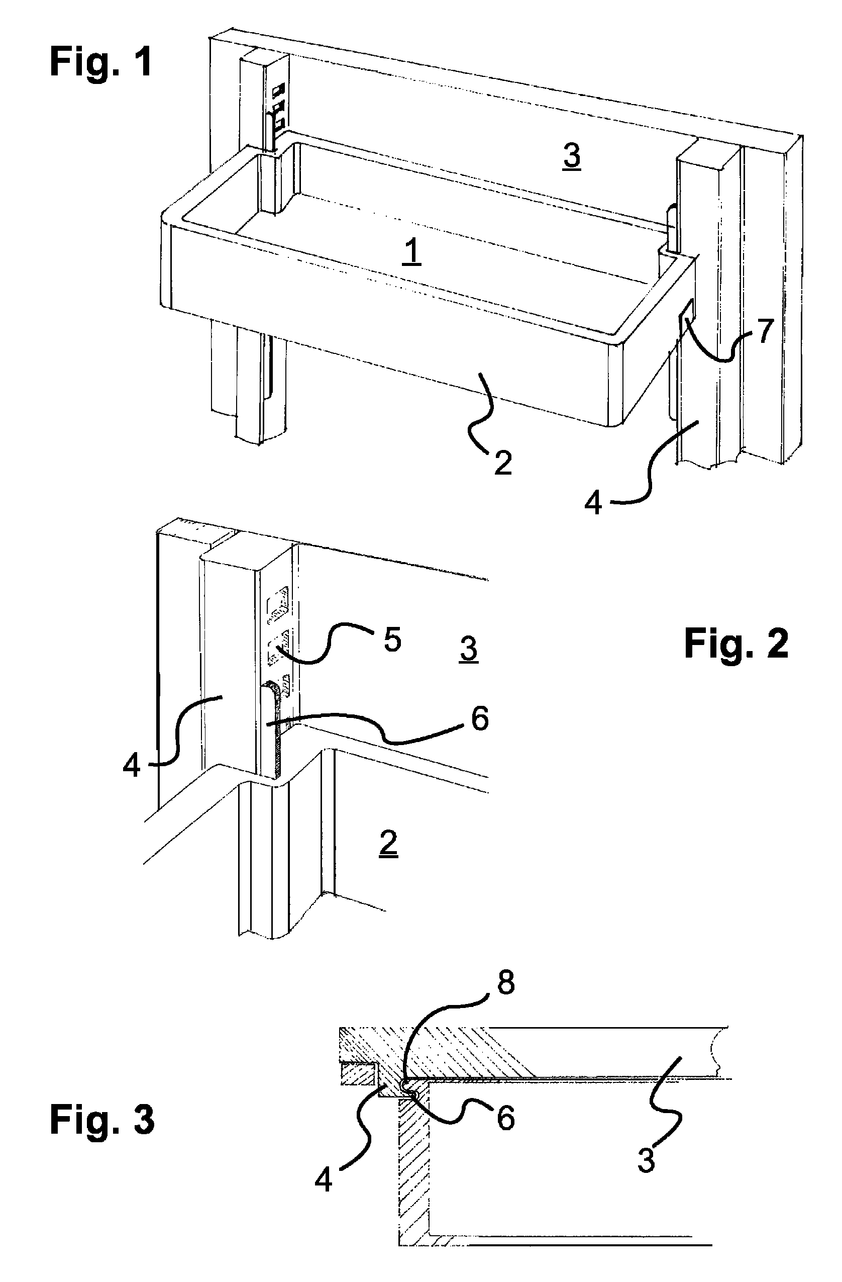
[0009]In a further advantageous embodiment the guide element is implemented on the support element as an undercut into which the door storage compartment can be suspended. The bar which forms the undercut serves especially advantageously here at the same time as a visualization for the adjustment range of the door storage compartment. It is also possible to provide the projecting element on the door storage compartment and have it engage in a groove on the support element. However a groove is less easily visible than a protruding bar and therefore gives a worse indication of the adjustment range. It is especially advantageous for the snap-in structure into which the snap-in projections of the door storage compartment can hook to be arranged on the support element precisely like the guide element. In this case both the snap-in structure and also the guide element can be mounted beforehand on the support element and arranged together with this on the refrigeration device door. This greatly simplifies the assembly of the entire door.

Problems solved by technology

Often however it is difficult to move these types of door storage compartments in the loaded state, since to do so they have to be taken out forwards, shifted and inserted again.

Method used


Image

  • Refrigeration device
  • Refrigeration device

Examples


Embodiment Construction

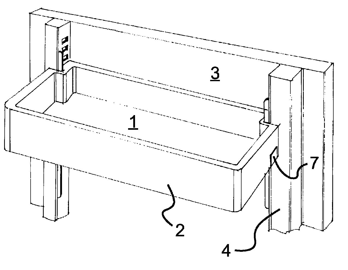
[0015]FIG. 1 shows the inner side of a refrigeration device door 3, with which two support elements 4 extending vertically running in parallel to each other are firmly connected. Furthermore a door storage compartment 1 with a frame 2 is provided. In each site section of the frame 2 a knob 7 is located close to the floor of the door storage compartment 1 which engages with a snap-in lug not visible in the figure. The snap-in lugs are located in the known manner in the rear area below the floor of the door storage compartment 1 and are pressed by a spring into a position in which they protrude sideways beyond the frame 2. The snap-in lugs together with the snap-in openings 5 of the support elements 4 form a snap-in structure.

[0016]In a preferred embodiment the support elements 4 possess a rectangular cross-section and feature snap-in openings 5 (FIG. 2). The snap-in openings 5 possess rectangular breakouts on the surface of the support element 4 which point in the direction of the ot...


PUM


Abstract

A refrigerator includes a door having a pair of lateral spaced supports on an inside of the door, and a height-adjustable door storage compartment removably securable via a snap-in structure to the inside of the door at locations between the pair of supports at a plurality of different heights, and a support having a vertically extending guide compatibly configured with a corresponding portion of the door storage compartment. The vertically extending guide and the corresponding portion of the door storage compartment engaging one another for orienting the door storage compartment relative to the door in an installed position of the door storage compartment on the door.

Description

BACKGROUND OF THE INVENTION[0001]The invention relates to a refrigeration device.[0002]Refrigeration devices, especially refrigerators, usually feature door storage compartments, i.e. storage drawers or storage containers for refrigerated items such as bottles, eggs, butter containers or other smaller refrigerated items which are fastened detachably to the door. Often these door storage compartments or arranged adjustable in height on the door of the refrigeration device so that the spacing of the door storage compartments on the refrigeration device door can be adapted to different sizes of refrigerated items to be stored therein. Mostly different attachment positions for the door storage compartments are provided for this purpose on the door of the refrigeration device, so that usually two different adjustments are produced per door storage compartment, which provides a degree of flexibility in the arrangement of the door storage compartments.[0003]However it is often desirable to...

Claims


Application Information

Patent Timeline
Patent Type & Authority Patents(United States)
IPC IPC(8): A47B96/04E06B1/00A47B9/00
CPCF25D23/04F25D23/067F25D25/04F25D25/02
Inventor BECKE, CHRISTOPH
Owner BSH BOSCH & SIEMENS HAUSGERAETE GMBH
Learn More