
Directional loudspeaker to reduce direct sound

a directivity control and loudspeaker technology, applied in the direction of transducer details, stereophonic arrangments, electrical transducers, etc., can solve the problems of affecting the sound reflection of the vehicle, affecting the sound environment inside the vehicle, and the placement of seats, passengers, etc., to achieve enhanced audio

Active Publication Date: 2012-02-21
HARMAN INT IND INC
View PDF35 Cites 8 Cited by
  • Summary
  • Abstract
  • Description
  • Claims
  • Application Information

AI Technical Summary

Benefits of technology

[0007]The disclosure provides an enhanced audio experience in an enclosed or partially enclosed environment with a multi-directional loudspeaker. One example of a multi-directional loudspeaker system includes a directional loudspeaker system. The loudspeaker may include loudspeaker elements that produce an indirect sound field greater than a direct sound field at a listener position. The loudspeaker elements may include dipole loudspeakers (such as electrodynamic planar loudspeakers). The loudspeaker elements may be mechanically baffled, or the loudspeaker elements may be configured with an acoustic waveguide and deflector to produce the indirect sound fields.

Problems solved by technology

The sound produced may be degraded because of the vehicle's interaction with the outside environment and the nature of the interior of the vehicle.
For example, exterior vehicle noise such as road noise, wind noise, and surrounding vehicle sounds may interfere with the sound environment inside the vehicle.
Specifically, the placement of seats, passengers, and vehicle structures such a pillars, windows, and headliners may affect sound reflections.
For audio systems that seek to reproduce multi-channel sound sources, or create an illusion of spaciousness within the vehicle, the available placement of speakers may not allow optimal, sound reproduction.

Method used


Image

  • Directional loudspeaker to reduce direct sound
  • Directional loudspeaker to reduce direct sound
  • Directional loudspeaker to reduce direct sound

Examples


Embodiment Construction

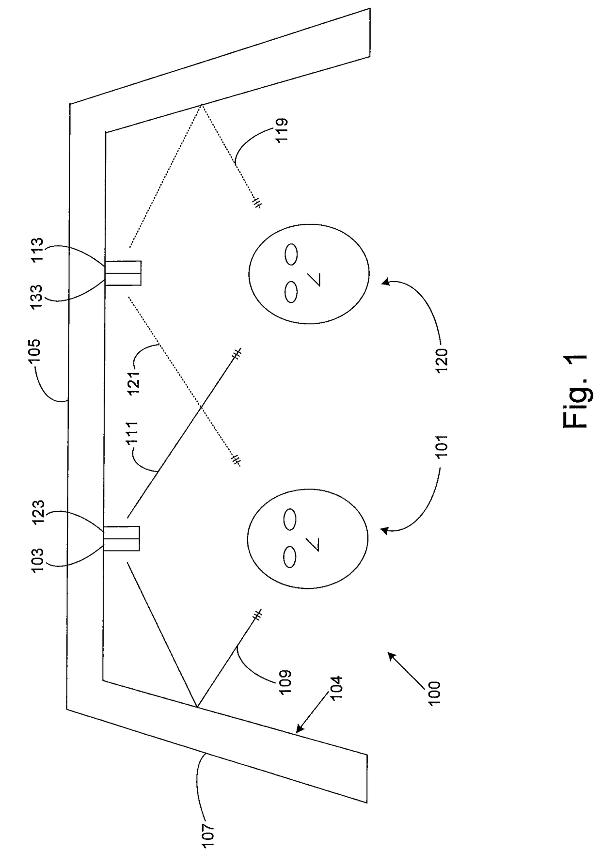
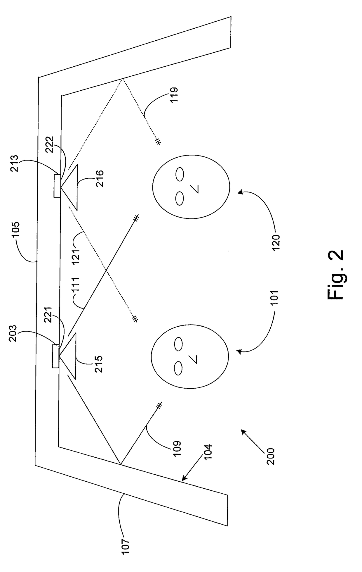
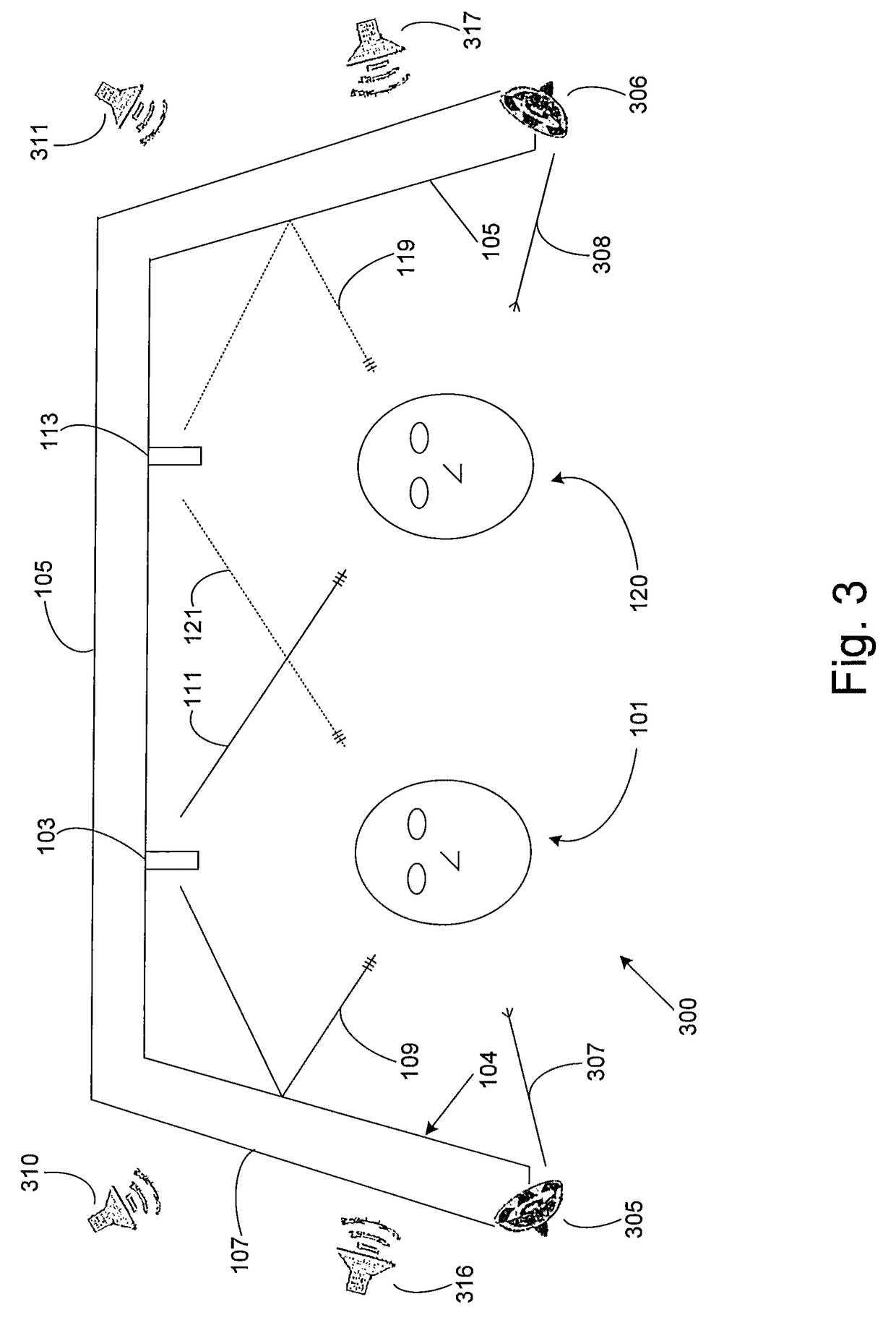
[0022]FIG. 1 illustrates an example directional loudspeaker 100. The loudspeaker system 100 may be placed in an enclosure, such as a vehicle or a home theater environment. The vehicle or home theater environment may have boundary walls 104 defining the enclosure. The boundary walls may be ceilings 105, floors, windows 107, and walls. The loudspeaker 100 is configured to include one or more listener positions 101 and 120 where a listener may experience the output from the loudspeaker 100. The loudspeaker 100 may include at least one loudspeaker element 103 and 113. A loudspeaker element 103 or 113 may include a second loudspeaker element 123 or 133 positioned near the loudspeaker element 103 or 113 respectively. The second loudspeaker element 123 and 133 may allow the loudspeaker element 103 and 113 to operate in phase with respect to the sound fields radiated from the loudspeaker.

[0023]The loudspeaker elements 103 and 113 are mountably positioned integral with the boundary wall prox...


PUM


Abstract

A directional loudspeaker provides an enhanced listening environment by producing an indirect sound field of greater amplitude than that of the direct sound field. The directional loudspeaker includes loudspeaker elements positioned to provide a listener located below the loudspeaker elements with an impression of sound spaciousness in a vehicle environment. The loudspeaker elements may include baffles or acoustic lenses to deflect the indirect field away from the path to the listener position. The loudspeaker may also be operated with windows open by channeling the indirect sound field through an acoustic waveguide and deflector to the listener. A sound processor is also provided to accept a sound input, create an indirect and direct sound field, output the sound fields to loudspeaker elements, and also may provide electronic enhancement effects such as multi-channel sound or sound parameter adjustment.

Description

BACKGROUND OF THE INVENTION[0001]1. Technical Field[0002]The invention relates to loudspeaker directivity control. In particular, the invention relates to a loudspeaker for generating an indirect sound field greater than a direct sound field.[0003]2. Related Art[0004]Loudspeaker systems may be included in a variety of environments. One type of environment is a vehicle in which the loudspeaker system is coupled to an audio system. Loudspeaker systems may be placed throughout the vehicle to produce sound in the vehicle. The sound produced may be degraded because of the vehicle's interaction with the outside environment and the nature of the interior of the vehicle. For example, exterior vehicle noise such as road noise, wind noise, and surrounding vehicle sounds may interfere with the sound environment inside the vehicle.[0005]As another example, the interior design and boundary walls of the vehicle may affect the acoustics of a vehicle audio system. Specifically, the placement of sea...

Claims


Application Information

Patent Timeline
Patent Type & Authority Patents(United States)
IPC IPC(8): H04R1/02H04B1/00
CPCH04R1/025H04R1/345H04R5/02H04R2201/021
Inventor HUTT, STEVEN W.MIHELICH, RYANHOUSE, WILLIAM NEALARMITAGE, MARK JUSTIN
Owner HARMAN INT IND INC
Learn More