
Electric motor and electric pump unit with busbars integrally formed with driving circuit connecting terminals

a technology of connecting terminals and electric motors, which is applied in the direction of dynamo-electric converter control, dynamo circuit shape/form/construction, piston pumps, etc., can solve the problems of increasing the number of parts, hindering the lightness and compactness of the electric motor, and the connection system of a coil. , to achieve the effect of reducing the number of parts and realizing lightness and compactness

Active Publication Date: 2012-02-21
JTEKT CORP
View PDF21 Cites 9 Cited by
  • Summary
  • Abstract
  • Description
  • Claims
  • Application Information

AI Technical Summary

Benefits of technology

The invention is an electric motor with a simplified connection system between the coils and external driving circuit, reduced number of parts, and lightweight and compactness. The motor includes a stator core, coils of multiple phases, insulator, and busbars. The busbars are integrally formed with driving circuit connecting terminals, which are directly connected to the external driving circuit for controlling the driving current. The driving circuit connecting terminals are in the shape of a flat plate that comes into surface contact with the driving circuit board, ensuring positive electrical contact. The driving circuit board is disposed at an end of the insulator, making the space between the driving circuit connecting terminals and the axial direction of the rotor and stator core thin and compact. The busbars are fixedly buried in the insulator, eliminating protruding parts. The driving circuit connecting terminals are provided with through holes and nuts for easy fixation of the driving circuit board to the insulator. The invention also includes an electric pump unit with the electric motor for driving the pump portion.

Problems solved by technology

Thereby, a connection system from a coil that constitutes each phase to an external driving circuit in an electric motor becomes complicated, and the number of parts increases.
Further, lightness and compactness of the electric motor will be hindered due to the output terminal blocks having the harness slots, and the space occupied by the output terminal blocks.

Method used


Image

  • Electric motor and electric pump unit with busbars integrally formed with driving circuit connecting terminals
  • Electric motor and electric pump unit with busbars integrally formed with driving circuit connecting terminals
  • Electric motor and electric pump unit with busbars integrally formed with driving circuit connecting terminals

Examples


Embodiment Construction

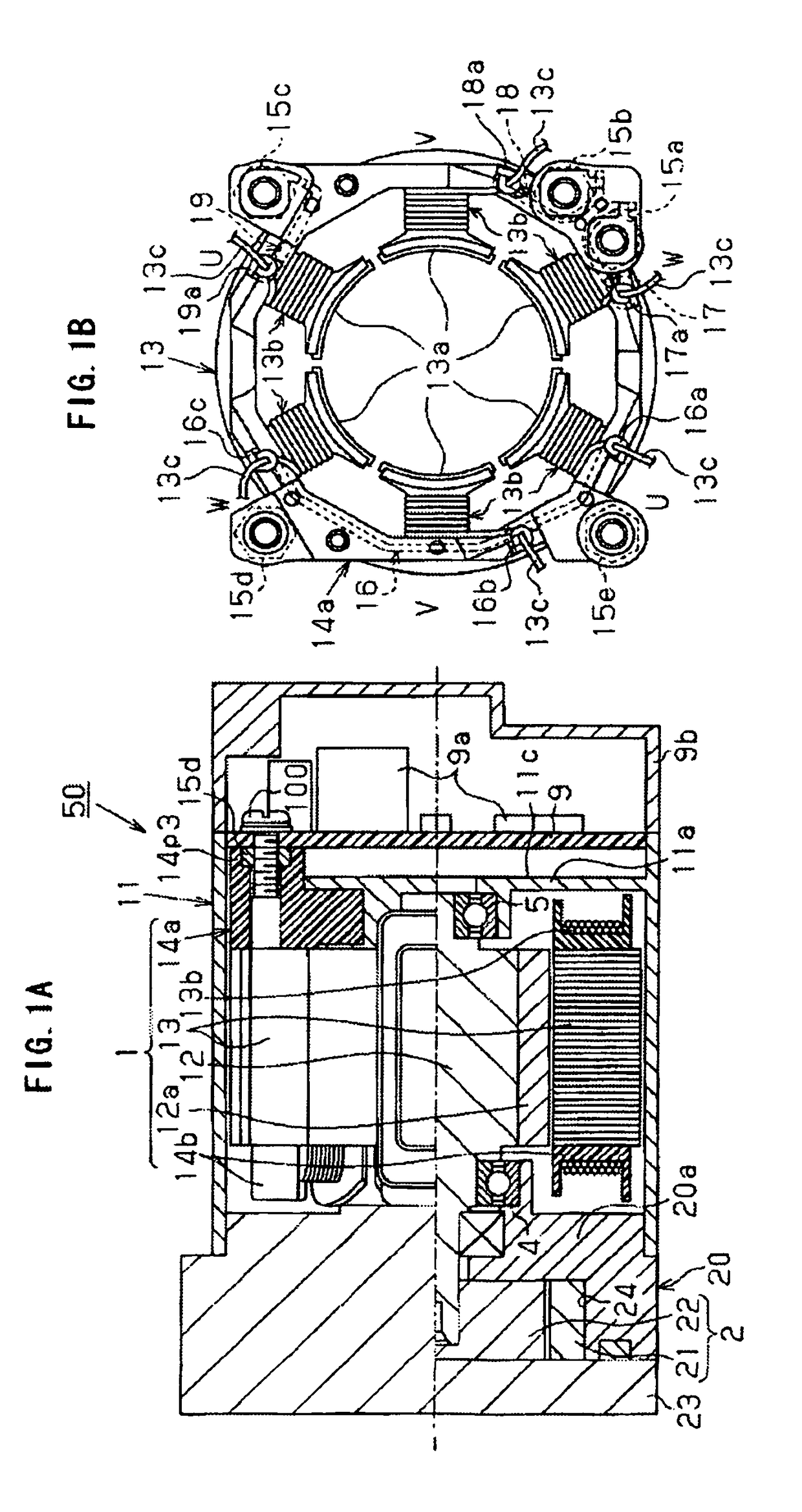
[0030]Hereinafter, embodiments of the invention will be explained according to the drawings. As shown in FIGS. 1A and 1B, an electric motor 1 of the embodiment is used for an electric pump unit 50 used as a hydraulic pump for a transmission of an automobile.

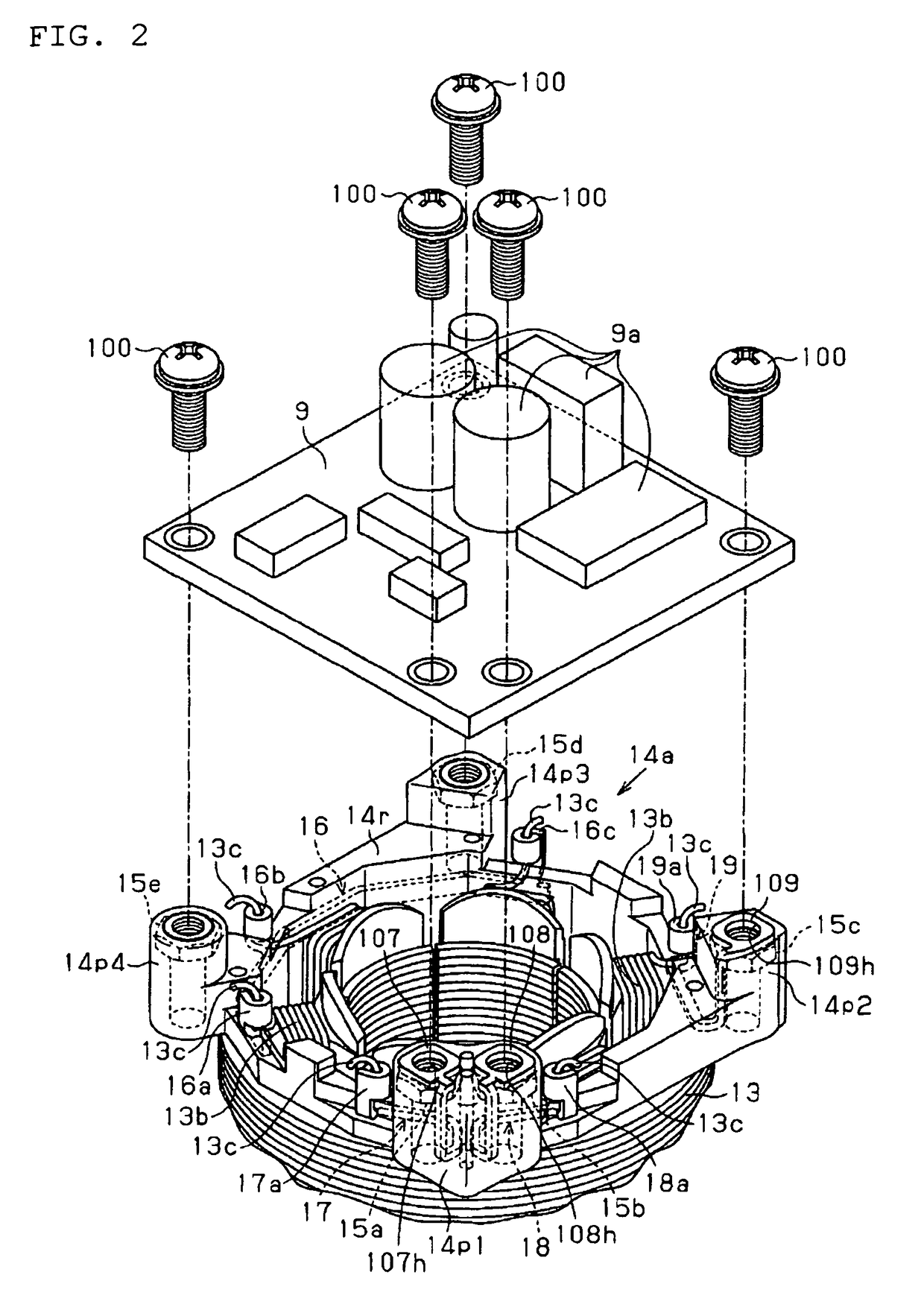
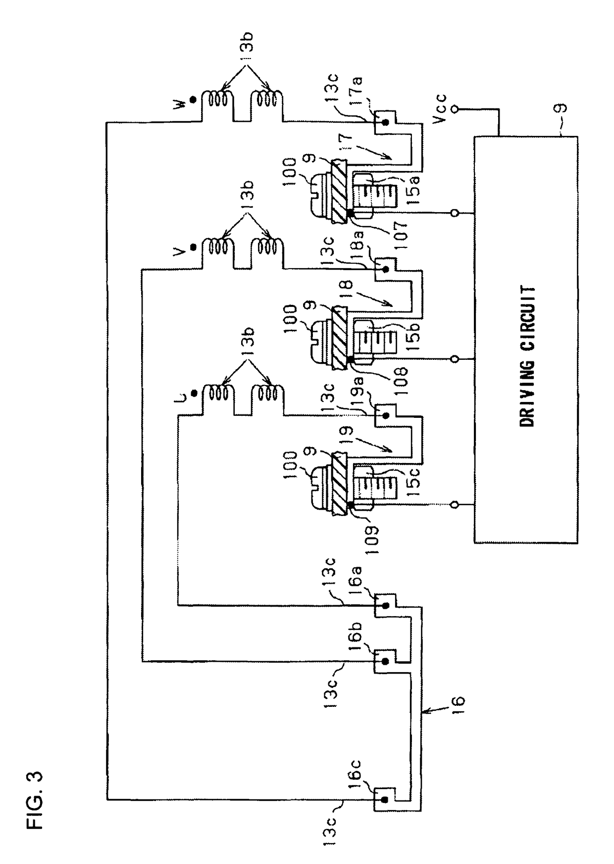
[0031]The electric motor 1 includes a rotor 12, a stator core 13 that surrounds the stator 12, and coils 13b that are wound around six (a plurality of) teeth 13a of the stator core 13. Moreover, the electric motor 1 includes a pair of tubular insulators 14a and 14b that are fitted from axial opposite ends of the stator core 13 so as to insulate each coil 13b and the stator core 13 (teeth 13a), and is accommodated in a bottomed quadrangular tubular motor case 11. In addition, referring to FIG. 1B, the electric motor 1 constitutes a three-phase brushless motor, and three pairs of facing coils 13b constitute a U phase, a V phase, and a W phase, respectively. Further, in this embodiment, the insulators 14a and 14b are formed by injec...


PUM


Abstract

The invention provides an electric motor including a tubular insulator that insulates coils of each of U, V, and W phases that makes a rotor rotated by an electromagnetic force, and a stator core around which the coils are wound; and a plurality of busbars that are fixed to the insulator to relay feed of power to the coils that constitute each phase. Ring-shaped terminals directly connected to an external driving circuit board for controlling a driving current leading to each phase of the coils, without via separate connecting members, are integrally formed in the busbars, respectively.

Description

BACKGROUND OF THE INVENTION[0001]The present invention relates to an electric motor including busbars serving as relay members that relay electrical connection between a driving circuit for controlling a driving current that leads to coils that make a rotor rotated by an electromagnetic force, and the coils, and further relates to an electric pump unit including the electric motor.[0002]As an electric motor that has busbars used as relay members that relay electrical connection with an external driving circuit, etc., an electric motor described in, for example, JP-A-2005-27413 is known. This electric motor includes three-phase circuit lead wires (busbars) electrically connected to three coils that surround a rotor and constitute U, V, and W phases, respectively. The three-phase circuit lead wires are fixedly welded to internal terminals, are electrically connected to three harness slots provided in output terminal blocks that are adjacent to one another in the axial direction of the...

Claims


Application Information

Patent Timeline
Patent Type & Authority Patents(United States)
IPC IPC(8): H02K3/38H02K3/32
CPCH02K3/522H02K11/0073H02K2203/03H02K2203/06H02K2211/03H02K11/33
Inventor SAKATA, TAKATOSHI
Owner JTEKT CORP
Learn More