
Intermaxillary fixation device and method of using same

a technology of fixation device and intermaxillary, which is applied in the field of devices, can solve the problems of significant discomfort and dental injury potential, both methods suffer drawbacks, and the wire ligature itself is uncomfortable, and the mandible fracture is reduced, so as to reduce the fracture and reduce the fracture

Active Publication Date: 2012-02-21
MARCUS JEFFREY R
View PDF25 Cites 21 Cited by
  • Summary
  • Abstract
  • Description
  • Claims
  • Application Information

AI Technical Summary

Benefits of technology

This solution provides a more comfortable, efficient, and stable method for IMF, allowing for secure anchoring to bone and flexible application of elastics for occlusion restoration, reducing the risk of injury and improving patient outcomes in maxillofacial procedures.

Problems solved by technology

However, both methods suffer drawbacks.
This is a time-consuming process, associated with significant discomfort and potential for dental injury.
The wire ligatures themselves are uncomfortable and often must be adjusted / tightened by the treating physician.
Removal of arch bars applied using CW's, is equally uncomfortable; there is further associated potential for dental injury; in some, removal requires operative anesthesia.
While orthodontic adhesives are known, they too have disadvantages, in large part due to the conditions under which IMF is performed.
Both techniques may be severely limited or even precluded in conditions for dental injury, loss, or preexisting poor dental health.
However, IMF screws do not provide stability along the dental arch as does an arch bar.
For fractures occurring between teeth, IMF screws do not provide upper border stabilization nor flexible technical application methods to optimize occlusion.
Finally, it is difficult (if not impossible) to apply elastics between IMF screws.

Method used


Image

  • Intermaxillary fixation device and method of using same
  • Intermaxillary fixation device and method of using same
  • Intermaxillary fixation device and method of using same

Examples


Embodiment Construction

[0039]Arch bars are described for providing stabilization and / or fixation between the mandible and maxilla using device(s) affixed to bone (native or graft) or prosthedontic appliances for use in applications including, but not limited to, treatment of fracture, restoration and fixation of dental occlusion, and maxillary and / or mandibular reconstruction with or without bone grafts. The arch bars may be affixed to bone, thus precluding the need for CW, or the use of adhesives.

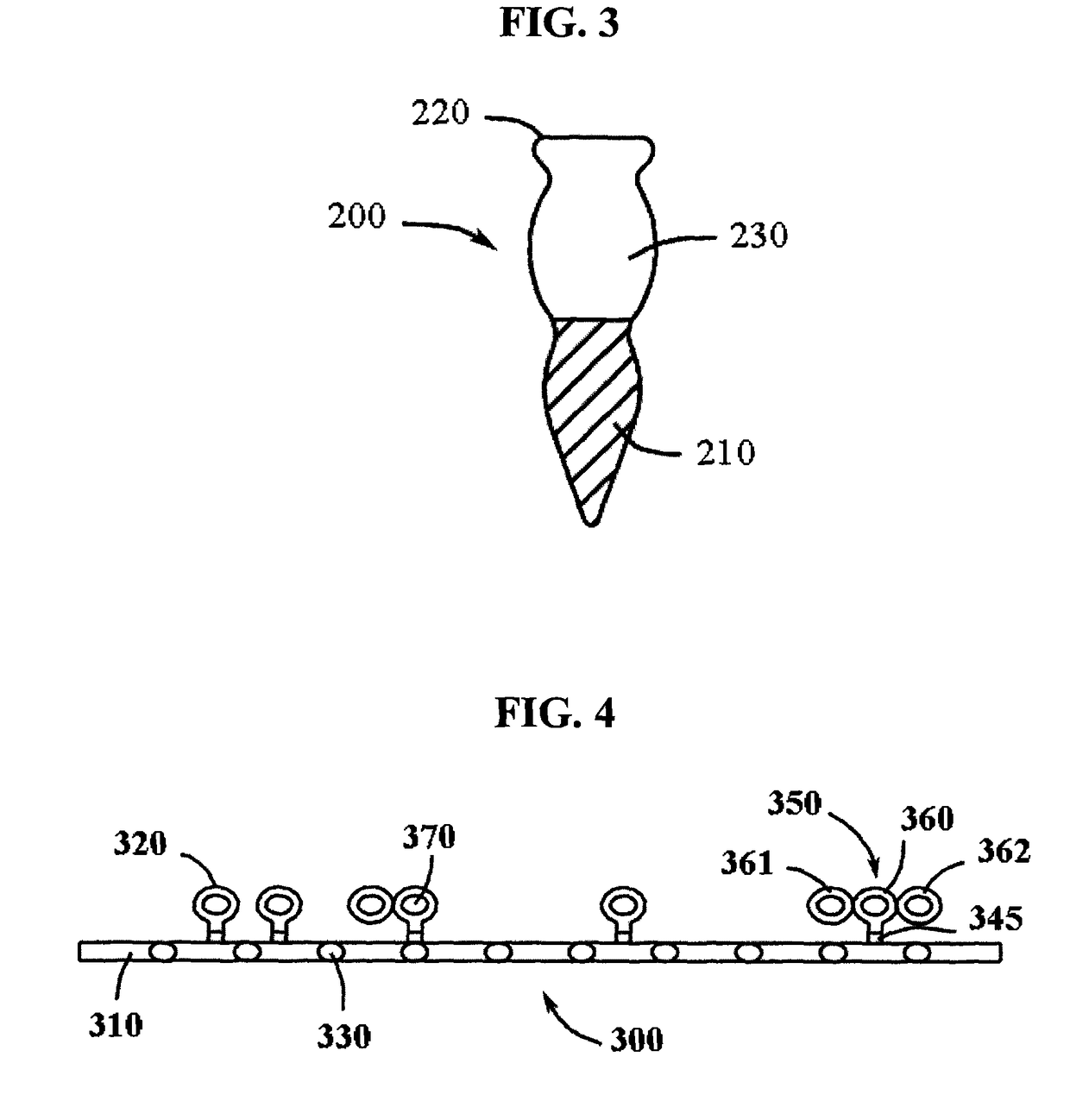
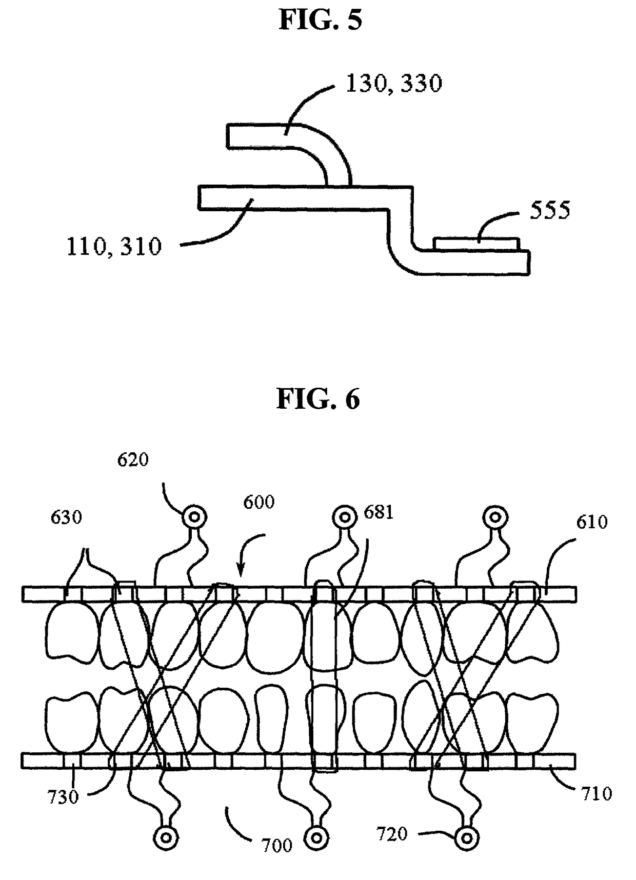
[0040]As shown in FIG. 1, and according to one embodiment, an arch bar 100 is a bar 110 having a first attachment loop 120, a second attachment loop 121, and a plurality of hooks 130. The first attachment loop 120 is distally located to the second attachment loop 121 such that each end of the bar, may be secured to a bone such a mandible or maxilla, or a prosthedontic apparatus via the first and second attachment loops 120, 121. The attachment loops 120, 121 may be attached to the bar 110 via a stem 140, 145 tha...


PUM


Abstract

A medical apparatus for intermaxillary fixation or stabilization has a bar with a first attachment loop, a second attachment loop, and a plurality of hooks, wherein the bar is an arch bar and the first attachment loop and the second attachment loop are located distally to one another. Another medical apparatus has a bar having a first attachment loop assembly, a second attachment loop assembly, and a plurality of hooks, wherein the bar is an arch bar and the first attachment loop assembly and the second attachment loop assembly are movably engaged to the bar. The bar may also have one or more additional attachment loop assemblies located between the first and second attachment loop assemblies. The attachment loop assemblies may each have a bracket, an attachment loop, a stem, and a set screw. The attachment loops are capable of receiving a screw to attach the arch bar to a mandible, a maxilla, and / or a prosthedontic device.

Description

CROSS-REFERENCE TO RELATED APPLICATIONS[0001]This application claims the benefit of U.S. Provisional Patent Application Nos. 61 / 012,557, filed Dec. 10, 2007, and 61 / 012,561, filed Dec. 10, 2007, the entire contents of which are incorporated herein by reference for any and all purposes.FIELD[0002]The invention is generally related to maxillofacial / dental devices. More specifically, the invention is related to devices for the maxillary and / or mandibular fixation or stabilization.BACKGROUND[0003]The fixation or stabilization of the upper and lower dental occlusal arches to one another is known as intermaxillary fixation (IMF), also known as maxillo-mandibular fixation (MMF). IMF has historically been a necessity in the treatment of all reconstructive jaw procedures.[0004]The earliest methods for providing IMF consisted of wiring techniques, in which metallic wires were placed around one or more (adjacent) teeth at their base(s) and were then twisted down to the teeth in a secure manner...

Claims


Application Information

Patent Timeline
Patent Type & Authority Patents(United States)
IPC IPC(8): A61B17/04A61B17/84A61F2/08
CPCA61C5/007A61F5/05891A61C7/00A61C8/0096A61B17/60A61B17/8605A61C7/36
Inventor MARCUS, JEFFREY R.
Owner MARCUS JEFFREY R
Learn More