Fastening device

a technology of fastening device and handle, which is applied in the direction of earth drilling and mining, drilling accessories, drilling machines and methods, etc., can solve the problems of difficult to apply sufficient force to the handle, forward and rearward acting, electronic staple devices, etc., and achieve the effect of convenient use of the fastening devi

Active Publication Date: 2012-02-21
LMN SOLUTIONS
View PDF18 Cites 7 Cited by
  • Summary
  • Abstract
  • Description
  • Claims
  • Application Information

AI Technical Summary

Benefits of technology

[0010]Fastening devices in accordance with the present invention allow a user to squeeze the handle to generate energy within the device and maintain that energy within the device as potential energy. When desired, the user can actuate a manually operable latch, which allows the potential energy stored within the device to be converted to kinetic energy in order to allow the ejection of a fastener. This allows users to more easily use a fastening device such as a manually operable staple gun for applications that were previously difficult. There are several known methods in which to generate potential energy for use in fastening devices.

Problems solved by technology

However, the input load required to depress the handle is identical to, or substantially the same as, rearward acting staplers and is therefore still substantial.
There are certain drawbacks to conventional forward and rearward acting staplers.
Oftentimes it may be difficult to apply sufficient force to the handle if one is outstretched or in some other awkward stance, or if one is trying to fasten onto a backing that is not rigidly supported.
Electronic staple devices, however, suffer the disadvantage of, among other things, requiring a power source and the commensurate weight penalty which comes with the ancillary mechanisms required for proper and safe operation.
These conventional staple guns, however, do not allow a user to store the energy within the staple gun in one step and then release the stored energy in an independent step.
For example, if the user of a staple gun is required to apply a fastening device or staple above the user's head or just out of the user's reach, the user would not be able to use traditional manual staple guns to apply the fastening device with much success.

Method used


Image

  • Fastening device
  • Fastening device
  • Fastening device

Examples


Embodiment Construction

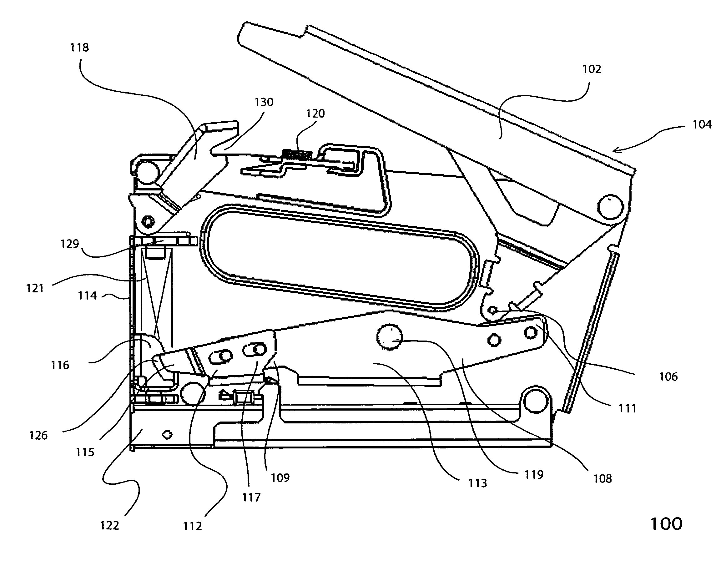
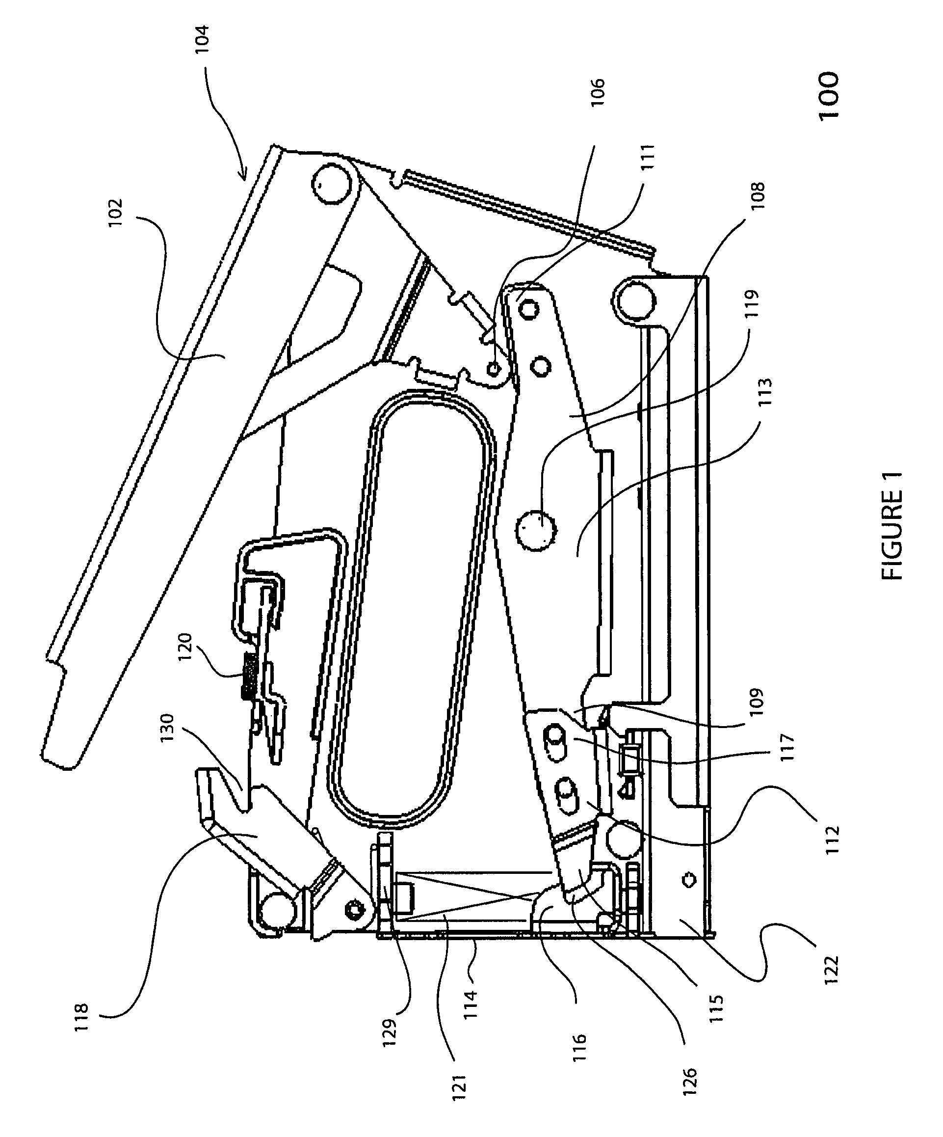
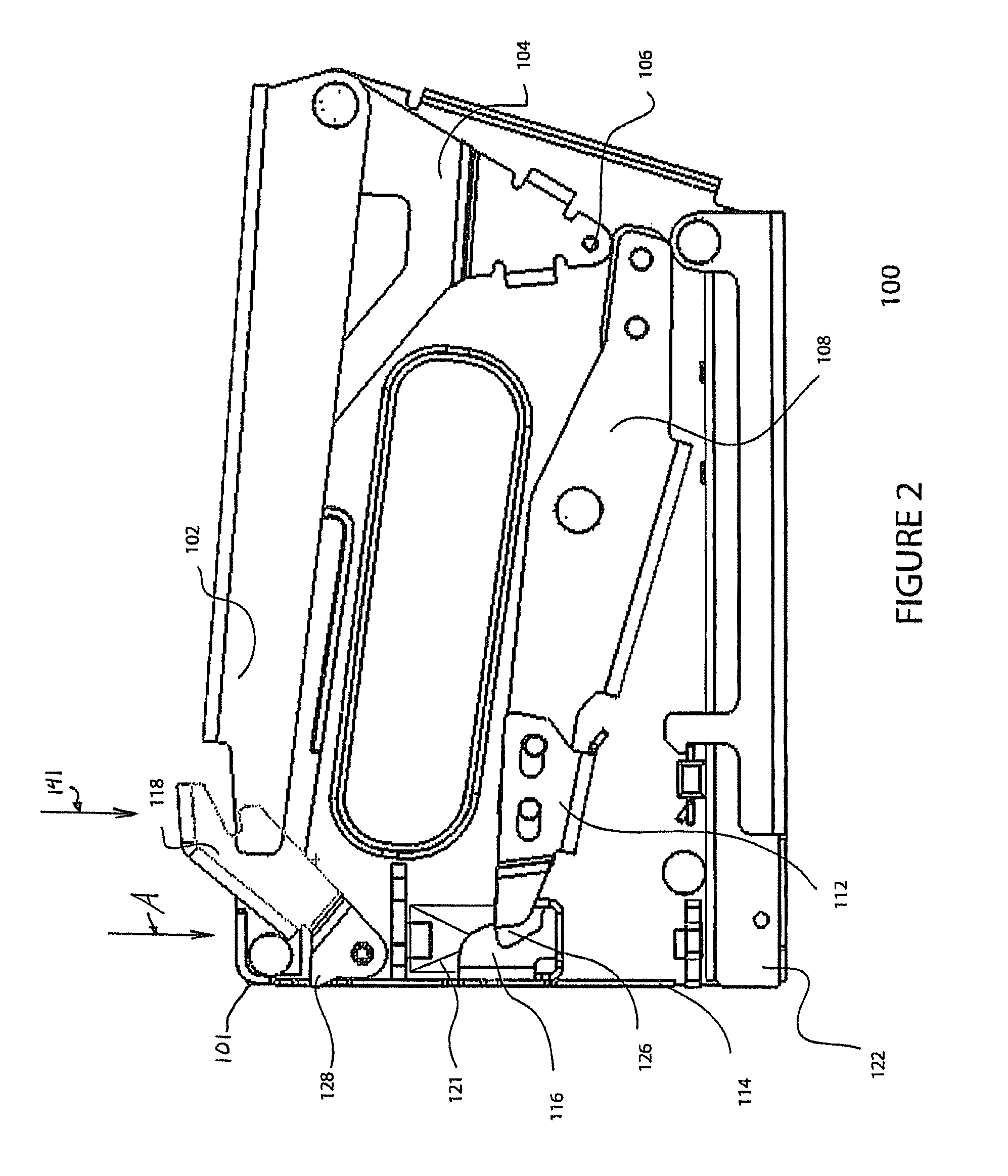
[0019]In accordance with an embodiment of the present invention, a fastening device, such as a forward acting stapler, is provided that includes a manually operable latch. The latch functions to retain potential energy stored in a compression spring of the fastening device created by operation of a manually operated handle. Upon actuation of the latch, the plunger within the fastening device is released, thereby converting the potential energy stored in the compression spring into kinetic energy and displacing a fastener (such as, for example, staples, nails or other types of fasteners) from the staple cartridge or magazine and forcefully dispelling the fastener from the device.

[0020]A fastening device 100 is shown in FIG. 1. In the embodiment shown, the fastening device 100 is a manually operable staple gun and in particular, a forward acting manually operable staple gun. The fastening device 100 includes a handle assembly 104 that includes a manually operable handle portion 102, w...


PUM


Abstract

In accordance with an embodiment of the present invention, a fastening device such as, for example, a forward acting stapler, is provided that includes a manually operable latch in order to store the built up potential energy that results from depressing the handle of the fastening device. Upon actuation of the latch, the plunger within the fastening device is released, thereby converting the stored energy of an internal compression spring into kinetic energy and ejecting a fastener (such as, for example, staples, nails or other types of fasteners) from the staple chamber to fasten an object.

Description

[0001]This application claims the benefit of U.S. provisional application No. 60 / 800,735, filed May 16, 2006.FIELD OF THE INVENTION[0002]The present invention relates to the field of fastening tools of the type employed to drive fasteners (such as, for example, staples, nails or other types of fasteners) into various work surfaces.BACKGROUND OF THE INVENTION[0003]Fastening tools, such as, for example, manually operated staple guns, allow an operator of the device to use a single hand in order to operate a handle or the like. Movement of the handle causes the compression of a spring in the tool. When the energy in the spring is released, a fastener is expelled from the fastening device. The operation of the handle to compress the spring and the subsequent release of the energy built up in the spring typically results from one motion of the handle. One type of fastening tool is a forward acting stapler, which is commonly known in the art, and has a handle which is pivoted at one end, ...

Claims


Application Information

Patent Timeline
Patent Type & Authority Patents(United States)
IPC IPC(8): B25C5/06
CPCB25C5/06B25C5/11
Inventor POPOWICH, DAVID J.
Owner LMN SOLUTIONS
Why Eureka
Try Eureka