On-vehicle electronic control device

a technology of electronic control device and vehicle, which is applied in the direction of vehicle position/course/altitude control, process and machine control, instruments, etc., can solve the problems of excessive control burden of communication control, needless transmission, slow abnormality judgment, etc., and achieve the effect of reducing the control burden

Active Publication Date: 2012-02-14
MITSUBISHI ELECTRIC CORP
View PDF10 Cites 3 Cited by
  • Summary
  • Abstract
  • Description
  • Claims
  • Application Information

AI Technical Summary

Benefits of technology

[0014]The present invention has been made in order to address these problems, and it is a first object thereof to obtain an on-vehicle electronic control device configured to efficiently and frequently transmit digital conversion values of many analog signals such that accurate A / D conversion information is obtained while reducing the control burden.
[0015]It is a second object of the present invention to obtain an on-vehicle electronic control device configured to accurately transmit, using communicating means of a typical word length, digital conversion data of a long bit resulting from a multichannel A / D converter including high-accuracy resolution.
[0028]Consequently, there are the effects that, because normal data are collectively transmitted to the second buffer memory for report transmission after the multichannel A / D converter completes the series of A / D conversions and the normal data are prepared, erroneous data can be prevented from being transmitted and creating confusion, and communication congestion resulting from needles report communication can be avoided.

Problems solved by technology

Further, the analog / digital conversion device of JP-A No. 8-23276 has the drawback that, when attempting to obtain digital information of analog signals, it becomes necessary to transmit before hand a channel designation command each time, so the burden of communication control becomes excessive when attempting to obtain a lot of digital information frequently.
Moreover, the analog / digital conversion device of JP-A No. 8-23276 also has the drawback that abnormality judgment is slow and needless transmission must be performed because it is configured to perform abnormality judgment of the A / D converter after it has transmitted A / D-converted digital information.
Moreover, the ultrasound diagnostic device of JP-A No. 2002-209886 is configured to divide A / D conversion data into a high-order bit group and a low-order bit group, transmit the groups, and combine the groups at the reception side, but when the timing of data division is asynchronous with the A / D conversion timing, there is the risk that data division abnormality will occur, so that when the groups are combined at the reception side, the high-order bit group of old data and the low-order bit group of new data become combined as one data group, for example.

Method used


Image

  • On-vehicle electronic control device
  • On-vehicle electronic control device
  • On-vehicle electronic control device

Examples


first exemplary embodiment

(1) Detailed Description of Configuration of First Exemplary Embodiment

[0041]A first exemplary embodiment of this invention will be described below.

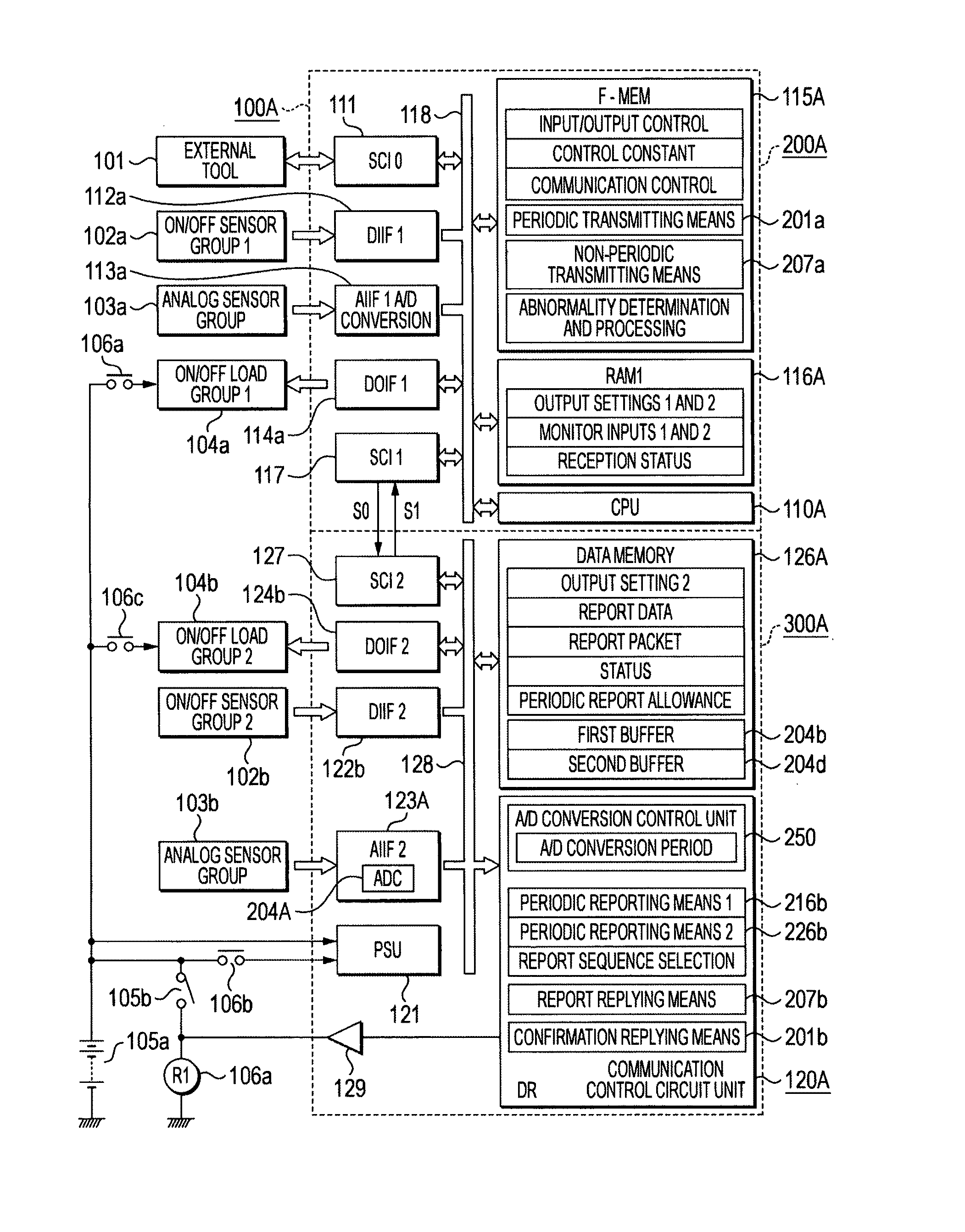
[0042]FIG. 1 is a total block diagram showing an on-vehicle electronic control device 100A according to a first embodiment of this invention.

[0043]In FIG. 1, the on-vehicle electronic control device 100A is configured by a first control circuit unit 200A and a second control circuit unit 300A.

[0044]Turning first to that which is connected to the outside of the on-vehicle electronic control device 100A, an external tool 101 is connected via an unillustrated detachable connector to the on-vehicle electronic control device 100A at the time of product shipment or at the time of maintenance. The external tool 101 is for transferring and writing control programs and control constants to a later-described nonvolatile program memory 115A.

[0045]A first input sensor group 102a is a sensor group that ON / OFF operates at a relatively high speed and r...

second exemplary embodiment

(1) Detailed Description of Second Exemplary Embodiment

[0193]FIG. 5, which shows a total block diagram of a second exemplary embodiment of this invention, will be described with attention given to differences with the on-vehicle electronic control device of FIG. 1.

[0194]FIG. 5 is a total block diagram showing an on-vehicle electronic control device 100B according to the second exemplary embodiment of this invention.

[0195]In FIG. 5, the main differences are that, whereas the communication control circuit unit 120A of FIG. 1 was configured by an integrated circuit element using a logic circuit, the on-vehicle electronic control device 100B of FIG. 5 includes an auxiliary CPU 120B and simple input / output control means is added to the second control circuit unit, but the same reference numerals represent the same or corresponding portions.

[0196]In FIG. 5, the on-vehicle control device 100B is configured by a first control circuit unit 200B and a second control circuit unit 300B. A micro...


PUM


Abstract

An on-vehicle electronic control device 100A serially transmits A / D conversion data of plural channels from a second control circuit unit 300A including a multichannel A / D converter 204A to a microprocessor 110A disposed in a first control circuit unit 200A. The A / D conversion data are organized into a communication packet and transmitted via first and second buffer memories 204b and 204d, and when there is an abnormality in the A / D conversion data, transfer between the first and second buffer memories 204b and 204d is prohibited and an abnormality report is performed with respect to the microprocessor 110A. As a result, erroneous data are not transmitted, and communication congestion and the burden of the microprocessor 110A are alleviated.

Description

BACKGROUND[0001]1. Technical Field[0002]The present invention relates to an on-vehicle electronic control device such as an engine control device configured such that electrically divided first and second control circuit units serially exchange monitor and control signals with each other, and more particularly to the improvement of an on-vehicle electronic control device for efficiently and accurately transmitting digitally converted analog signals.[0003]2. Related Art[0004]An on-vehicle control device is publicly known which is configured such that electrically divided first and second control circuit units serially exchange monitor and control signals by a periodic transmission packet that is a downlink communication, a periodic report packet that is an uplink communication, and a report reply packet that is an uplink communication corresponding to a read request packet that is a downlink communication.[0005]For example, Japanese Patent Application Publication (JP-A) No. 2003-2857...

Claims


Application Information

Patent Timeline
Patent Type & Authority Patents(United States)
IPC IPC(8): G06F3/00G06F5/00
CPCG06F13/126
Inventor IWAGAMI, YUKIWATANABE, TETSUSHITANAKA, JUNYAYAMASHITA, MANABUHASHIMOTO, KOJI
Owner MITSUBISHI ELECTRIC CORP
Why Eureka
Try Eureka