
Radio frequency identification based personnel safety system

a radio frequency identification and safety system technology, applied in the direction of safety devices for lifting equipment, electric signalling details, lifting devices, etc., can solve the problems of unsatisfactory previous attempts to reduce the frequency of workplace injuries caused by moving equipment, and the previous attempts to use rfid tags to enhance the safety of personnel working around moving equipment proved unsatisfactory

Inactive Publication Date: 2012-02-14
PSST MOBILE EQUIP - RICHARD SHERVEY
View PDF33 Cites 44 Cited by
  • Summary
  • Abstract
  • Description
  • Claims
  • Application Information

AI Technical Summary

Problems solved by technology

It is well known that larger equipment moving at faster speeds poses a greater risk to other personnel working in the same vicinity.
Previous attempts to reduce the frequency of workplace injury from moving equipment have not been satisfactory.
As set out above, previous attempts to use RFID tags to enhance the safety of personnel working around moving equipment have proved unsatisfactory.
Previous systems employing RFID tags have not been sufficiently tied in to the operating system of the piece of equipment and therefore have only provided an audible warning to the operator of the equipment or the individual wearing the RFID tag when the worker gets too close to the equipment.
Due to the loud noise levels at many such worksites, these types of audible signals may be insufficient to adequately ensure that the piece of equipment does not continue to strike the worker.
In addition, there has been resistance to implementing immobilization of such equipment in response to proximity of RFID tags due to the adverse impact that such immobilization will have on the productivity of the job site.
In particular, stopping the movement of a machine results in at least a portion of time during which the machine is not performing its intended function and therefore the overall efficiency of the industrial process is reduced.
An additional difficulty with prior uses of RFID tags for safety devices has been the location of only a single RFID tag at a point source locatable on the user.
Such a point source RFID tag may be susceptible to being screened or blocked from being read by an antenna on a vehicle depending on the orientation of the body of the worker wearing such a tag and therefore may potentially result in a false negative reading for the presence of an RFID tag.
Such a false negative reading may in turn lead to the piece of equipment striking and injuring the worker.

Method used


Image

  • Radio frequency identification based personnel safety system
  • Radio frequency identification based personnel safety system
  • Radio frequency identification based personnel safety system

Examples


Embodiment Construction

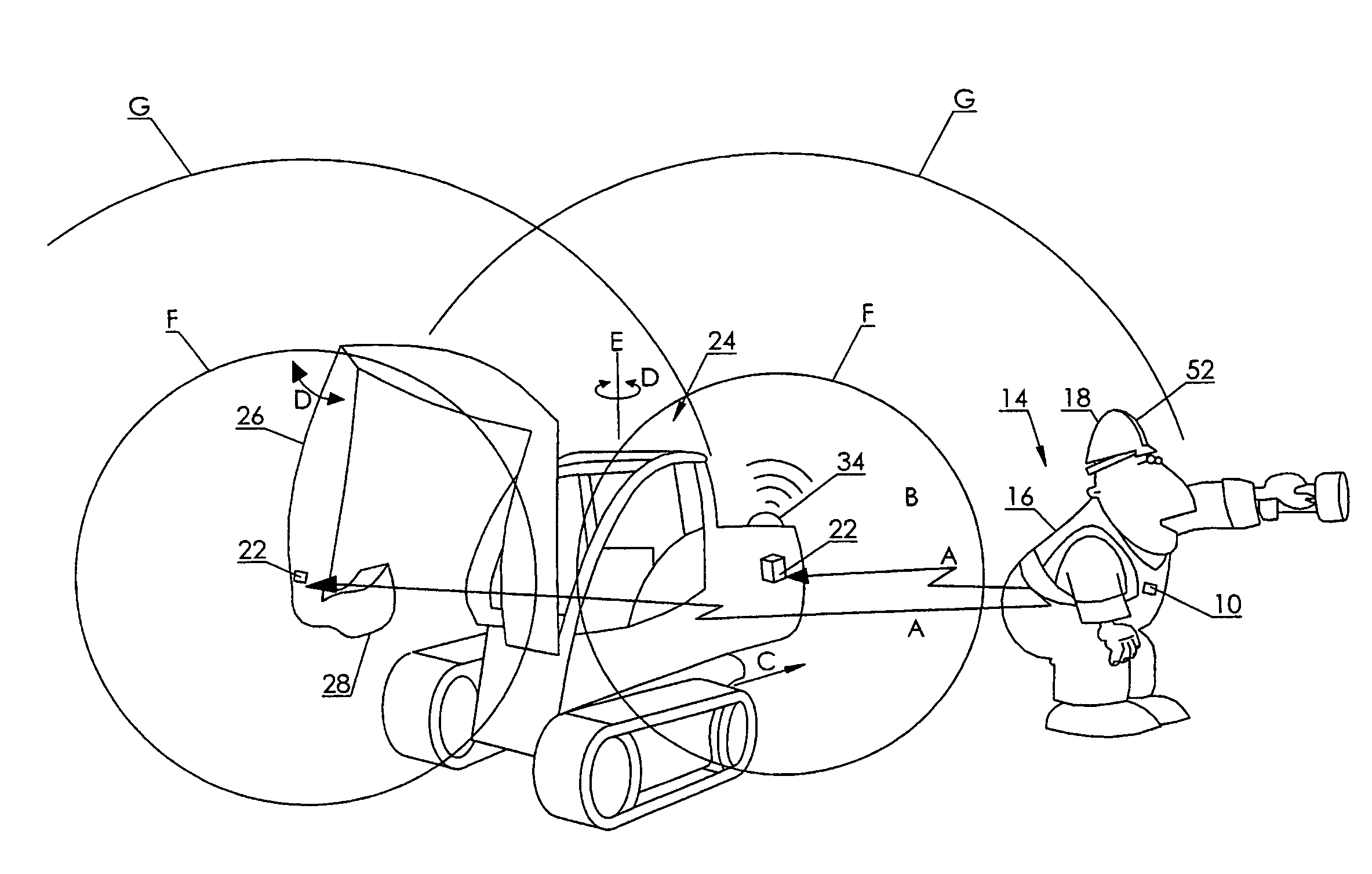
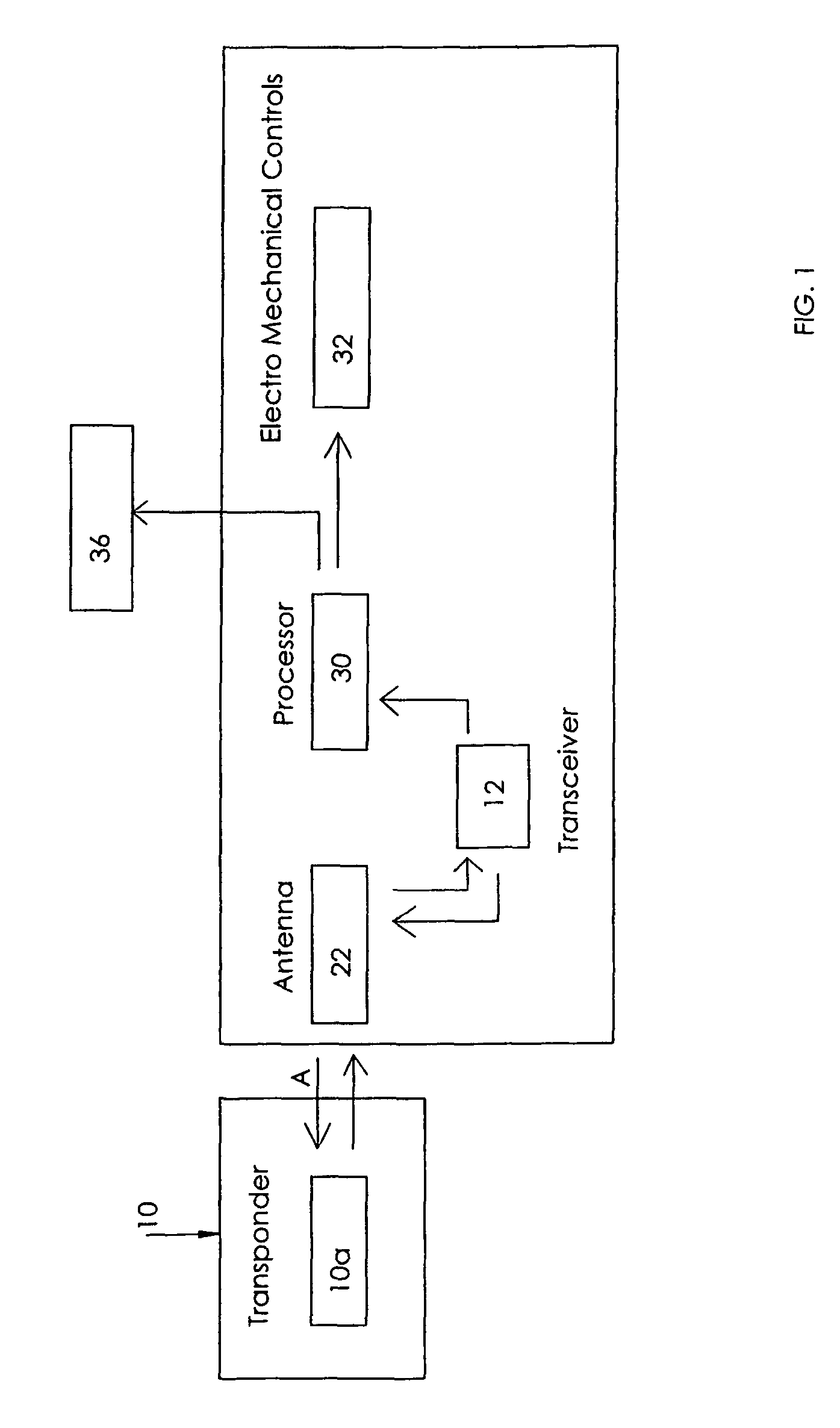
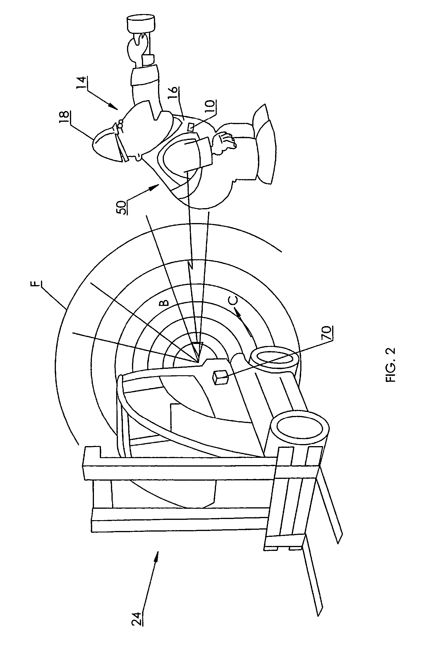
[0035]As seen in the accompanying Figures, wherein similar characters of reference denote corresponding parts in each view, the RFID based personnel safety system according to one aspect of the present invention includes an RFID tag 10 which contains a transponder 10a. The tag may for example be worn by a workman 14 either on an item of clothing 16, or on a hardhat 18 or the like.

[0036]Transponder 10a within tag 10 is in discontinuous radio frequency communication such as indicated by arrow line A with a transponder detection system 20. Transponder detection system 20 includes at least one antenna 22, which, in a preferred embodiment, may be one or more directional antennas, cooperating with transceiver 12.

[0037]In the case of use of a single antenna, it can be an omnidirectional antenna, unidirectional antenna, or, preferably, a directional antenna, such as for example a dipole antenna or yagi antenna taught in the prior art, for increased directionality and range.

[0038]Multiple an...


PUM


Abstract

Disclosed is a method and apparatus for selectively immobilizing equipment to ensure the safety of a proximate worker. The apparatus comprises an article of clothing wearable by the proximate worker, a sensor and a stopping means for stopping the movement of a portion of the equipment in response to the sensing. The article of clothing has a RFID tag having an antenna distributed about the article so as to substantially surround a worker wearing the article of clothing. The sensor senses the proximity of the RFID tag to a portion of the equipment. The method comprises sensing the proximity of the RFID tag to a portion of the equipment and stopping the movement of a portion of the equipment in response to the sensing.

Description

CROSS REFERENCE TO RELATED APPLICATION[0001]This application claims priority from U.S. Provisional Patent Application No. 60 / 819,641 filed Jul. 11, 2006 entitled Radio Frequency Identification Based Personnel Safety System.FIELD OF THE INVENTION[0002]This invention relates to the field of devices insuring personnel safety, and in particular to a method and apparatus employing radio frequency identification based proximity sensing, warning and machine shut-down for collision avoidance between personnel and articulated or mobile industrial machinery.BACKGROUND OF THE INVENTION[0003]Workplace safety is of great importance. As the demands for efficiency in ensuring competitiveness of industries increases, so too does the size of the equipment as well as the speed at which these pieces of equipment move. It is well known that larger equipment moving at faster speeds poses a greater risk to other personnel working in the same vicinity.[0004]Applicants are aware of statistics such as conta...

Claims


Application Information

Patent Timeline
Patent Type & Authority Patents(United States)
IPC IPC(8): G08B21/00
CPCF16P3/14G08B25/016F16P3/147F16P3/141G08B21/0213B66F17/003
Inventor DASILVA, JOHNSHERVEY, RICHARD CLAYTON
Owner PSST MOBILE EQUIP - RICHARD SHERVEY
Learn More