Energization control device and image forming apparatus

a control device and control device technology, applied in the direction of electrographic process devices, instruments, optics, etc., can solve the problems of consuming power of heat roller systems, affecting the fusing temperature of recording sheets, and a long time until the temperature of the fuser roller

Inactive Publication Date: 2012-02-07
CANON KK
View PDF6 Cites 2 Cited by
  • Summary
  • Abstract
  • Description
  • Claims
  • Application Information

AI Technical Summary

Benefits of technology

[0016]The present invention also provides a device configured to control power applied to a heater, where the power energization control device can keep the temperature ripple of a fusing device constant and reduce flicker caused by a change in the amount of power applied to the fusing device.
[0017]The present invention further provides a power energization control device which can change a power energization pattern so that a frequency used to make the power energization change becomes higher than the frequency corresponding to a high flicker sensitivity.

Problems solved by technology

However, due to the increased heat capacity, it takes a long time until the temperature of the fuser roller reaches a desired temperature.
Further, the heat roller system consumes power while waiting for image forming operations, so as to keep the fuser roller at a constant temperature.
Therefore, the temperature of the heater significantly affects the fusing temperature of the recording sheet.
However, since the amount of power applied to the heater is changed with relatively high speed, the occurrence of flicker often becomes significant.
The heating device used for the image forming apparatus consumes a relatively large amount of power, such as 1000 W or around.

Method used


Image

  • Energization control device and image forming apparatus
  • Energization control device and image forming apparatus
  • Energization control device and image forming apparatus

Examples


Embodiment Construction

[0033]Hereinafter, embodiments of the present invention will be described with reference to the attached drawings.

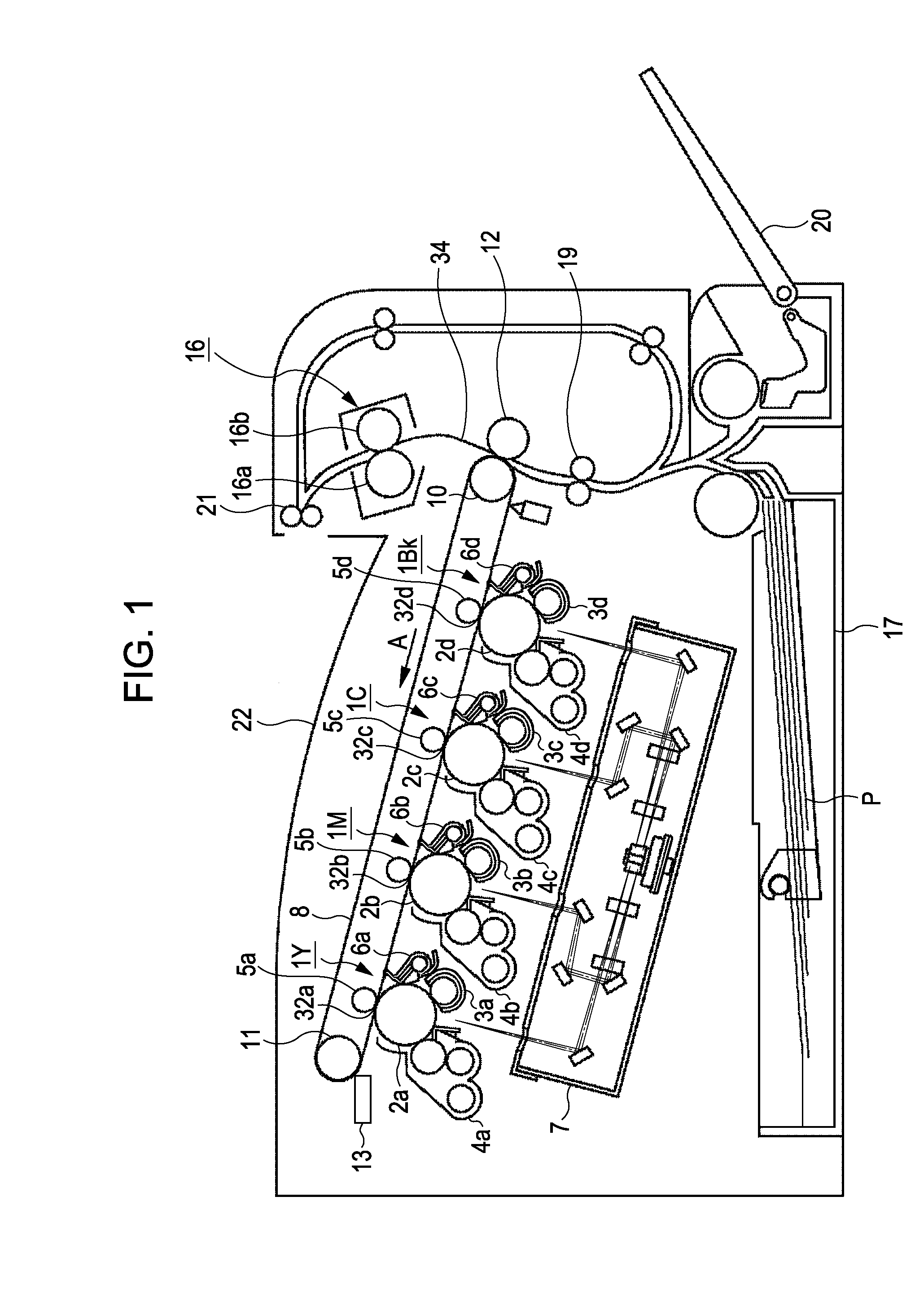
[0034]FIG. 1 is a schematic configuration diagram showing an electrographic color image forming apparatus according to an embodiment of the present invention. The above-described image forming apparatus includes four image forming units including an image forming unit 1Y configured to form an image having a yellow color, an image forming unit 1M configured to form an image having a magenta color, an image forming unit 1C configured to form an image having a cyan color, and an image forming unit 1Bk configured to form an image having a black color. The above-described four image forming units 1Y, 1M, 1C, and 1Bk are arranged in a line at regular intervals. The image forming apparatus includes paperfeed units 17 and 20 provided below the image forming units, where each of the paperfeed units 17 and 20 is configured to feed a recording sheet. The image forming apparatus fur...


PUM


Abstract

A heating unit heated upon receiving power supplied from an AC power supply, a temperature detecting unit detecting the temperature of the heating unit, a memory storing power energization pattern in which power energization and non-power energization are performed for each percentage of AC power, and a power control unit that determines the percentage of AC power applied to the heating unit based on the temperature and that determines the power energization pattern by referring to the memory are provided. When the power energization percentage is changed, the power control unit changes the power energization pattern after the power energization percentage is changed in accordance with the changed power energization percentage based on the power energization pattern before the power energization percentage is changed and the power energization pattern after the power energization percentage is changed.

Description

BACKGROUND OF THE INVENTION[0001]1. Field of the Invention[0002]The present invention relates to an energization control device configured to control power applied to a heater, and particularly relates to an image forming apparatus configured to control power applied to a fusing unit used during electrophotography process.[0003]2. Description of the Related Art[0004]A heat roller system has been widely used for an electrophotography copier, as a method of fusing an image on a recording material including a sheet of paper or the like. FIG. 2 is a sectional view of a fusing device using the heat roller system. A toner image formed on a photoconductor is transferred onto one of the faces of a recording sheet P. The above-described toner image is fused onto the recording sheet P by being heated and pressed when the recording sheet P is transmitted between a fuser roll 202 and a pressure roll 203 along the direction of an arrow A.[0005]The fuser roll 202 includes a cylindrical roll 202a ...

Claims


Application Information

Patent Timeline
Patent Type & Authority Patents(United States)
IPC IPC(8): G03G15/20H05B1/00
CPCG03G15/2039G03G2215/2035
Inventor YOSHIMOTO, TOTSUHIRO
Owner CANON KK
Why Eureka
Try Eureka