
Modular prosthesis and use thereof for replacing a radial head

a technology of radial head and prosthesis, which is applied in the field of prosthesis for replacing the proximal head of the radius, can solve the problems of radial head, proximal aspect of the radius, and frequent injury of the radial head,

Inactive Publication Date: 2012-02-07
BIOMET MFG CORP
View PDF373 Cites 15 Cited by
  • Summary
  • Abstract
  • Description
  • Claims
  • Application Information

AI Technical Summary

Benefits of technology

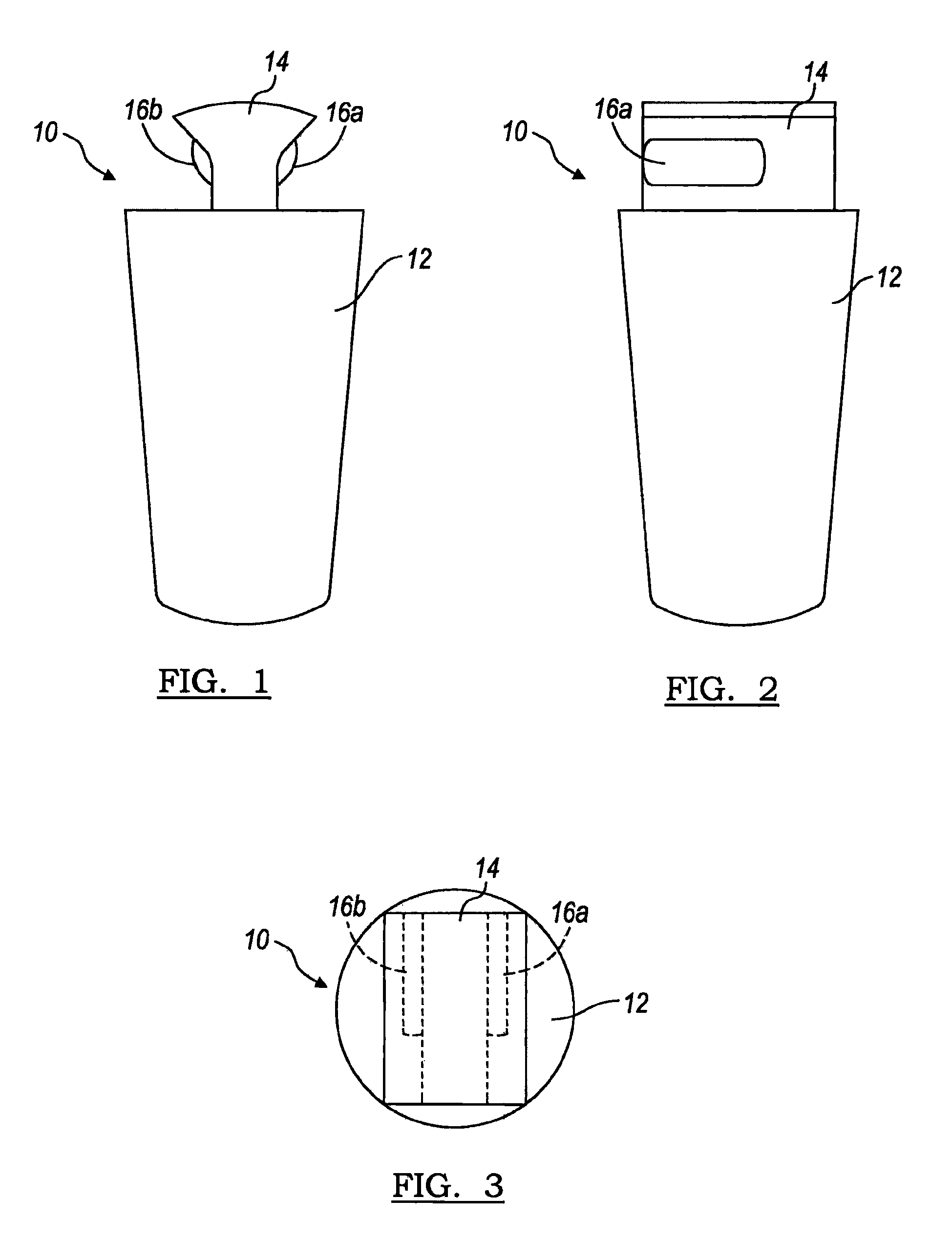
The patent describes a modular prosthesis system for replacing a head portion of a proximal radius. The system includes a monolithic stem component, a head component, and a locking mechanism. The stem component has a longitudinal axis and a dovetail-shaped mounting portion on its first end face that engages with a dovetail-shaped mounting portion on the head component. The locking mechanism is formed at the interface between the stem component and the head component and is engaged through relative translational movement between the stem component and the head component along the first direction. The technical effect of this invention is to provide a modular system that simplifies the replacement of a head portion of a proximal radius and improves the stability and securement of the prosthesis to the bone.

Problems solved by technology

Trauma to the elbow joint frequently involves damage to the ligamentous support of the elbow and fractures of the osseous structures responsible for the skeletal integrity of the elbow joint.
The proximal aspect of the radius, or radial head, is frequently injured either in isolation or in combination with injury to other bony or ligamentous structures of the elbow joint.
Whether in isolation or in combination with other injuries, fractures of the radial head can be difficult to treat.
Despite various technical advances in the reconstruction of radial head fractures, a certain percentage of fractures are not amenable to reconstruction due to the degree comminution or severity of the fracture.
In general, unreconstructable radial head fractures result from high energy trauma and are therefore frequently associated with significant injuries to other osseous or ligamentous structures of the elbow joint or forearm.
Further, silicone radial head prostheses were found to be incapable of resisting the stresses to which the radial head is subjected, rendering it less useful in stabilizing the injured elbow or forearm.
The difficulties apparent with silicone led to experimentation with metal radial head implants.
However, significant problems remain with these prostheses.
Therefore it has been difficult to restore appropriate anatomic alignments within the elbow.
Therefore restoration of the appropriate relationship between the capitellum and proximal shaft of the radius has been very difficult to achieve with these prostheses.
Additionally, the fact that these prostheses are fashioned from a single piece of metal has led to technical difficulties with insertion and removal.
Surgeons have had difficulty with matching both the size of the stem to the canal of the proximal radius and the size of the head portion to the patient's native radial head.
Thus the elbow is frequently destabilized during removal of these prostheses.
Increasing this distance alters the bony anatomy such that the ligaments of the elbow joint are not held in their appropriate lengths and tensions.
Instability of the elbow or inappropriate healing of the ligaments may result.
Furthermore, removal of these prostheses is accomplished in the same manner as the above mentioned metallic implants, often requiring destabilization of the lateral aspect of the elbow joint.

Method used


Image

  • Modular prosthesis and use thereof for replacing a radial head
  • Modular prosthesis and use thereof for replacing a radial head
  • Modular prosthesis and use thereof for replacing a radial head

Examples


Embodiment Construction

[0043]The following description of the preferred embodiment(s) is merely exemplary in nature and is in no way intended to limit the invention, its application or uses.

[0044]Before the present invention is disclosed and described, it is to be understood that this invention is not limited to the particular configurations, process steps and materials disclosed herein as these may vary to some degree. It is also to be understood that the terminology used herein is used for the purpose of describing particular embodiments only, and is not intended to be limiting as the scope of the present invention. The invention will be limited only by the appended claims and equivalents thereof.

[0045]It must be noted that, as used in this specification and the appended claims, singular forms of “a,”“an,” and “the” include plural referents unless the content clearly dictates otherwise.

[0046]“Radial head” is defined as the essentially cylindrical protrusion found at the proximal end of a radius bone. Th...


PUM


Abstract

A modular prosthesis system for replacement of a head portion of a proximal radius includes a monolithic stem component, a head component, and a locking mechanism formed by the stem and head components. The stem component defines a stem anchoring portion having a longitudinal axis and configured to couple to the proximal radius, and a dovetail-shaped first mounting portion on a first end face that extends in a first direction transverse to the longitudinal axis. The head component has a dovetail-shaped second mounting portion on a second end face opposite the first end face slidably engaged with the first mounting portion along the first direction. One of the first and second mounting portions intersects the longitudinal axis. The locking mechanism is formed at an interface between the stem and head components and is engaged through relative translational movement between the stem and head components. A related method is provided.

Description

CROSS-REFERENCE TO RELATED APPLICATIONS[0001]This application is a continuation of U.S. patent application Ser. No. 10 / 999,297, filed on Nov. 29, 2004, which is a continuation-in-part of U.S. patent application Ser. No. 10 / 464,043, filed Jun. 18, 2003 (now abandoned), which is a continuation of U.S. patent application Ser. No. 09 / 828,745, filed Apr. 9, 2001 now issued as U.S. Pat. No. 6,656,225 on Dec. 2, 2003, which claims the benefit of U.S. Provisional Application 60 / 195,444, filed on Apr. 10, 2000. The disclosures of the above applications and patents are hereby incorporated by reference as fully set forth herein.FIELD[0002]The present invention relates to prostheses for the elbow joint, and more specifically to prostheses for replacing a proximal head of the radius.BACKGROUND[0003]Trauma to the elbow joint frequently involves damage to the ligamentous support of the elbow and fractures of the osseous structures responsible for the skeletal integrity of the elbow joint. The prox...

Claims


Application Information

Patent Timeline
Patent Type & Authority Patents(United States)
IPC IPC(8): A61F2/38A61F2/00A61F2/30A61F2/46
CPCA61F2/3804A61F2/4637A61F2002/30387A61F2002/30604A61F2002/3827A61F2220/0025
Inventor BERELSMAN, BRIAN K.PARROTT, RUSSELL M.MARTIN, CHRISTOPHER H.LEE, DONALD H.GRAHAM, THOMAS J.
Owner BIOMET MFG CORP
Learn More