Ultrasonic welding tool with fluid drive

a technology of ultrasonic welding and ultrasonic motor, which is applied in the direction of mechanical control devices, instruments, process and machine control, etc., can solve the problems of inability to easily adjust the nominal pressure in the secondary chamber, the pressure exerted by the sonotrode, and the desired working pressure, etc., to achieve high-quality movement control

Active Publication Date: 2012-01-17
HERRMANN ULTRACHALLTECHNIK GMBH & CO KG
View PDF7 Cites 14 Cited by
  • Summary
  • Abstract
  • Description
  • Claims
  • Application Information

AI Technical Summary

Benefits of technology

[0013]On the basis of the afore-described prior art, the aim of the present invention is therefore to make available an ultrasonic welding tool with drive, which permits highly accurate movement control and which can also respond directly to sudden fluctuations of force and / or pressure.

Problems solved by technology

This mode of operation has the drawback that only the desired working pressure, i.e. the pressure which the sonotrode exerts upon the material to be processed, can be set.
However, the nominal pressure in the secondary chamber cannot be adjusted easily.
However, as a result of external factors, such as, for example, a variation in the thickness of the material to be processed, a change in working pressure can occur, and thus a change in the force to be applied, and this is not detected by the servo motor drive, thereby adversely affecting the weld result.
Even if a force sensor were to be provided as an alternative to, or in addition to, the positions sensor, control by means of a servo motor would find difficulty in counteracting sudden changes of pressure.

Method used


Image

  • Ultrasonic welding tool with fluid drive
  • Ultrasonic welding tool with fluid drive
  • Ultrasonic welding tool with fluid drive

Examples


Embodiment Construction

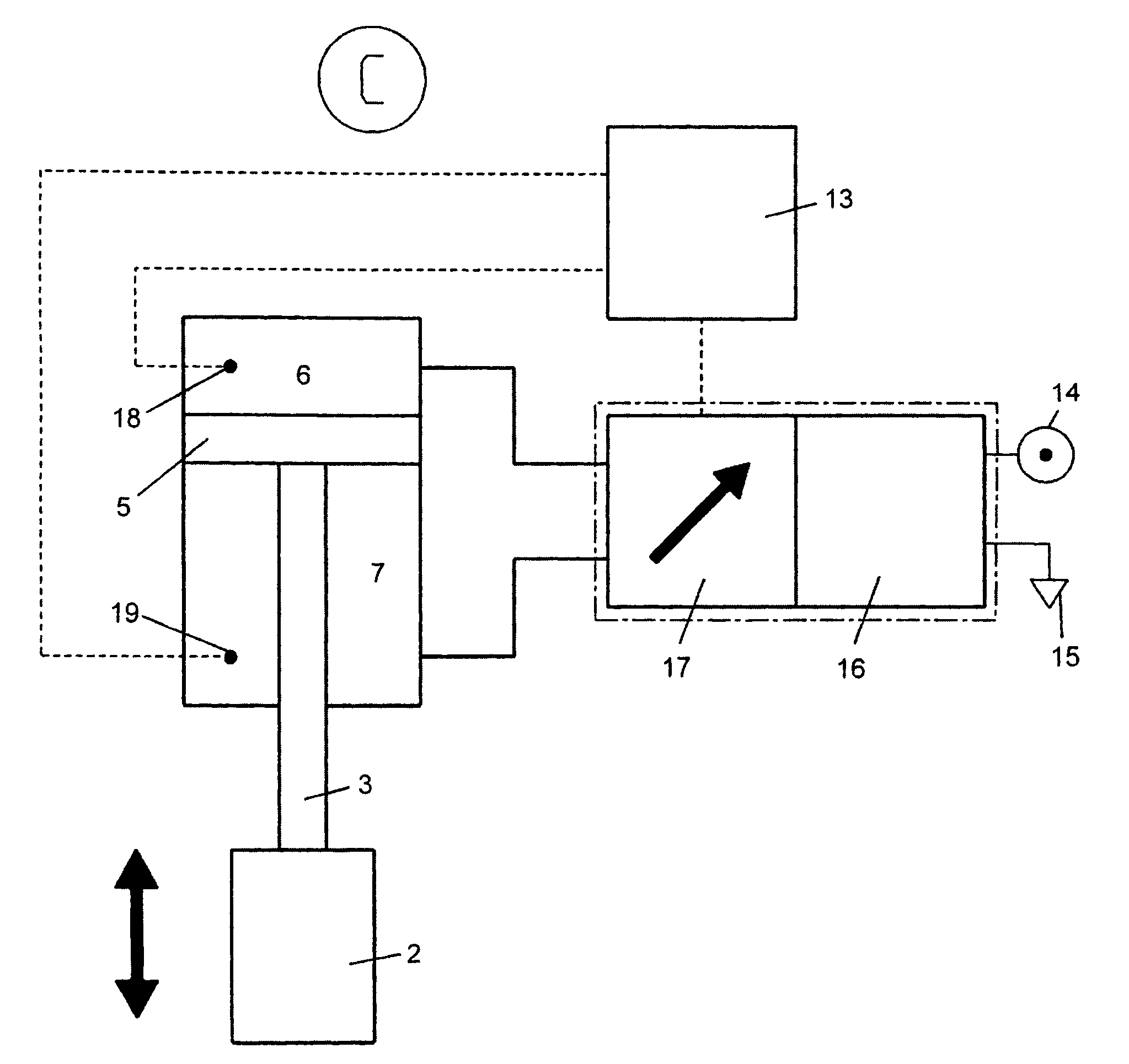
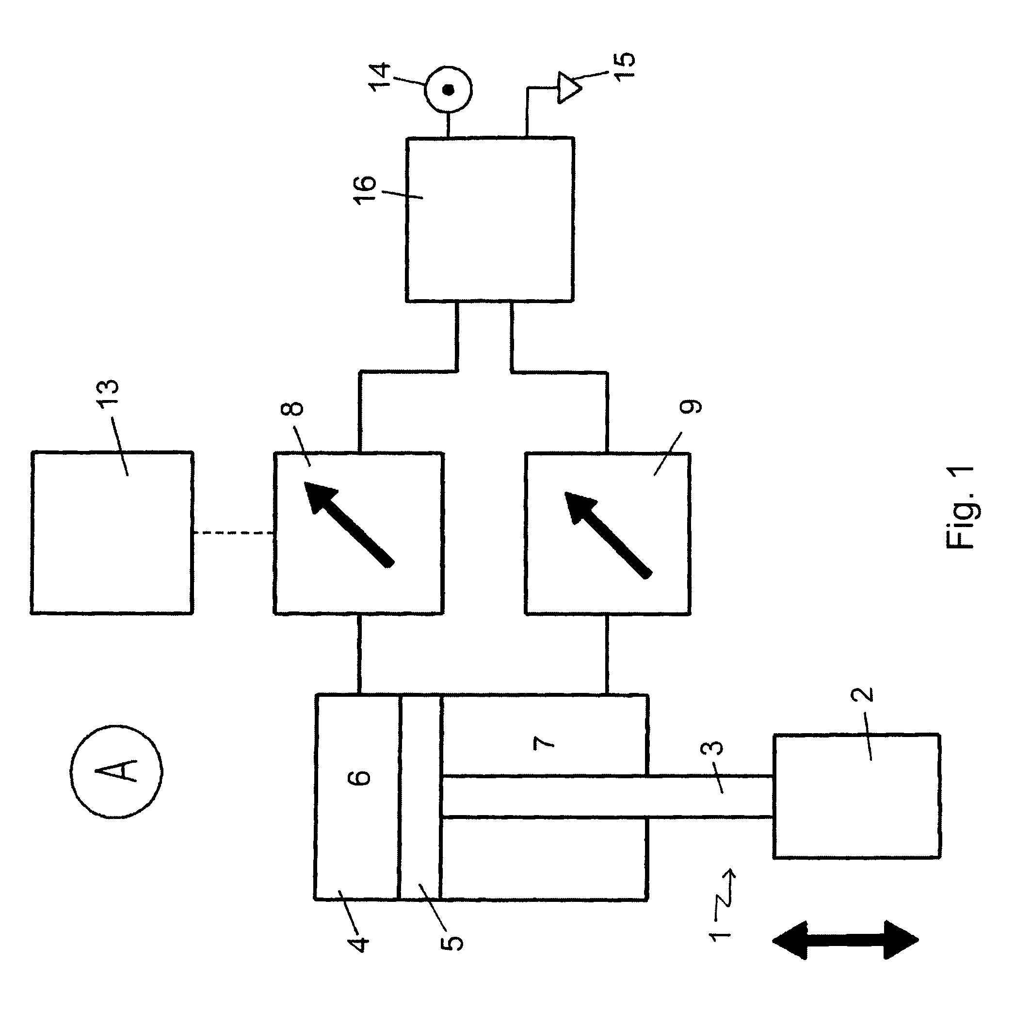
[0021]In one particularly preferred embodiment it is provided that the physical property detected is the ratio of the pressure in the primary chamber and the pressure in the secondary chamber.

[0022]In another particularly preferred embodiment it is provided that the physical property detected is the difference between the pressure in the primary chamber and the pressure in the secondary chamber.

[0023]Furthermore, for some applications, it can be advantageous if the physical property detected is the speed of the working piston. Alternatively, the physical property detected can be the position of the working piston.

[0024]In one particularly preferred embodiment, provided for the purpose of detecting two physical properties are two sensors, each of which emits an actual signal which is in relationship with the respectively detected physical property, wherein the first actual signal controls the two valves by way of a control circuit in such a way that the first physical property detect...


PUM

PropertyMeasurementUnit
physical propertyaaaaaaaaaa
pressureaaaaaaaaaa
speedaaaaaaaaaa

Abstract

An ultrasonic welding tool with fluid drive, wherein the ultrasonic welding tool (2) is connected by way of a piston rod (3) to a working piston (5) which is guided in a housing (4) of the drive, wherein the working piston (5) sub-divides the drive housing (4) into a primary chamber (6) and a secondary chamber (7), wherein each of the chambers is able to communicate by way of a valve (16) with a fluidized pressure source, wherein at least one sensor (18, 19) is provided for detecting a physical property of the fluid drive which sensor emits an actual signal which is in relationship with the physical property detected and which via a control circuit controls the two valves in such a way that the physical property detected follows a reference value profile.

Description

BACKGROUND OF THE INVENTION[0001]This application claims priority from German Application 102008015851.8, filed Mar. 27, 2008.[0002]The present invention relates to a fluid-driven ultrasonic welding tool, wherein the ultrasonic welding tool is connected by way of a piston rod to a working piston which is guided in a housing of the drive, wherein the working piston sub-divides the drive housing into a primary chamber and a secondary chamber, wherein each of the chambers is able to communicate by way of a valve with a fluidized pressure source.[0003]In this context, the term, “valve” means any device which is able to optionally connect or separate the chamber in question to or from the fluidized pressure source. Clearly, said function of the two valves can also be realized by one single control valve, by means of which it is possible to optionally connect either the primary chamber or secondary chamber to the fluidized pressure source. The term, “fluid” can refer to both gases and liq...

Claims


Application Information

Patent Timeline
Patent Type & Authority Patents(United States)
IPC IPC(8): B32B37/00
CPCB29C65/08B29C66/8242B29C66/9221B29C66/961B29C66/9261B29C66/9231B29C66/92443B29C66/8246B29C66/8322B29C66/8223
Inventor AUST, VOLKER
Owner HERRMANN ULTRACHALLTECHNIK GMBH & CO KG
Why Eureka
Try Eureka