
Imaging module for a projection system having an extended lens device rotatable from a first direction to one of a second and a third direction for selectively projecting image onto a screen

a projection system and module technology, applied in the field of projection system, can solve the problems of reducing the magnification effect affecting the image quality of the projection system, and unable to obtain the desired projection effect of the image pattern, etc., and achieves the effect of overcoming the shortcomings and disadvantages of conventional practices and achieving a larger magnification factor

Active Publication Date: 2012-01-10
DELTA ELECTRONICS INC
View PDF3 Cites 10 Cited by
  • Summary
  • Abstract
  • Description
  • Claims
  • Application Information

AI Technical Summary

Benefits of technology

[0011]With the above projection mechanism, images with display ratios reciprocal to each other can be projected along the second direction and the third direction respectively. Hence, such a projection system overcomes the shortcomings and disadvantages of conventional practices. In other words, such a projection system not only project images with common display ratios of 4:3 and 16:9, but also allows the user to preferably obtain images with display ratios of 3:4 and 9:16 and a larger magnification factor.

Problems solved by technology

But due to the limitation of output modes of digital devices, the length and width of the image pattern will be scaled down at equal ratios, which inevitably compromise the magnified display result of the projection system.
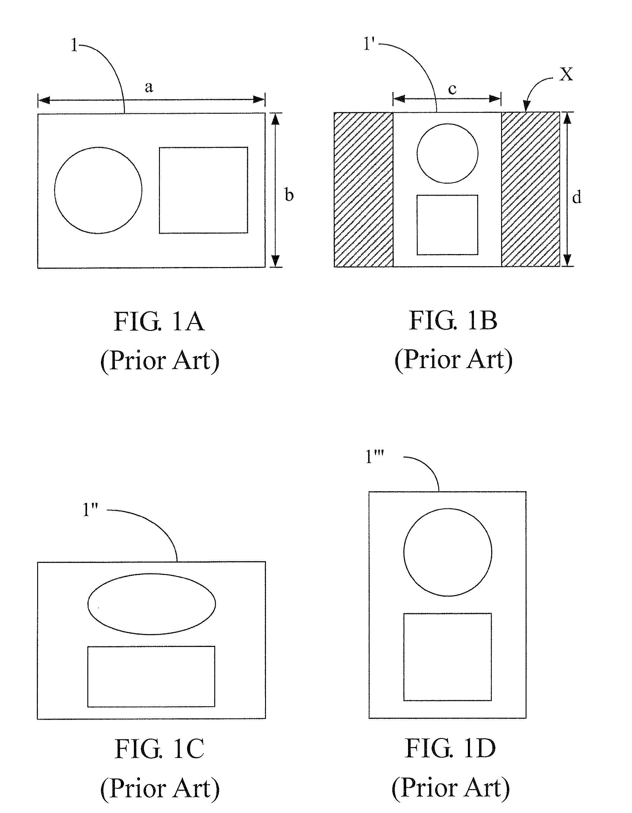
Meanwhile, because the second image 1′ is projected on a central area of the visible range of the projection screen X, shadows (as shown by the hatched portions in FIG. 1B) will appear in areas at both the left and the right sides of the projection screen X, making it impossible to obtain a desirable projection effect for the image pattern.
However, to sufficiently use the magnification capacity of the projection system, the second image 1′ with the display ratio of 3:4 would be modified by a software to fill up the projection screen with a ratio of 4:3, i.e., the first image 1 would be rotated 90° while still maintaining the original display ratio of 4:3 as shown in FIG. 1C, while the second image 1′ would be extended in the lateral direction to form a deformed third image 1″, leading to an incorrect display ratio and consequently a degraded viewing effect of the image.
However, to project images of the original display ratio again, the user has to revert the projection system to the original horizontal orientation, which is inconvenient and makes the projection system unstable due to the small seating area in the vertical orientation.
Besides the inconvenience and instability associated with changing the positioning orientation of the projection system, the bulb of the projection system needs to also be used at a particular angle.
An improper rotation of the projection system may cause shortened service life of or damage to the wick.
Moreover, this also has an adverse influence on heat dissipation in the projection system.
Unfortunately, rotating the positioning orientation of the projection system might block the vent holes, which compromise the effect of forced convection provided by the cooling fan, thus causing poor heat dissipation.
Consequently, because waste heat generated by components inside the projection system (especially the bulb) cannot be dissipated out of the projection system successfully and effectively, the accumulation of the waste heat within the projection system might damage to the projection system and shorten the service life thereof.
Therefore, the abovementioned practice for adjusting images is infeasible.
However, no effective solutions have been provided to increase the magnification factor of the image.

Method used


Image

  • Imaging module for a projection system having an extended lens device rotatable from a first direction to one of a second and a third direction for selectively projecting image onto a screen
  • Imaging module for a projection system having an extended lens device rotatable from a first direction to one of a second and a third direction for selectively projecting image onto a screen
  • Imaging module for a projection system having an extended lens device rotatable from a first direction to one of a second and a third direction for selectively projecting image onto a screen

Examples


Embodiment Construction

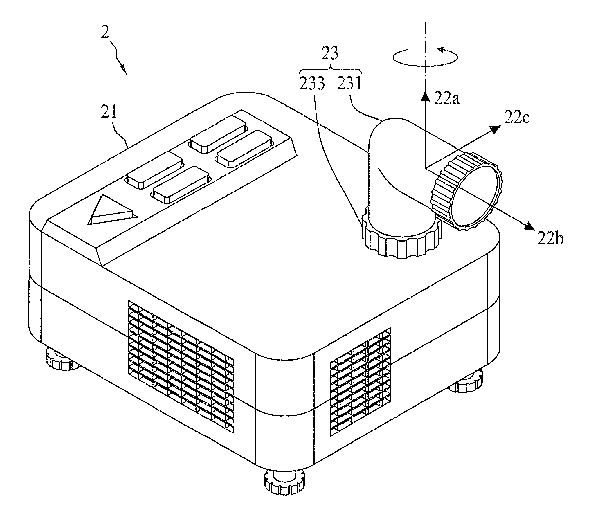
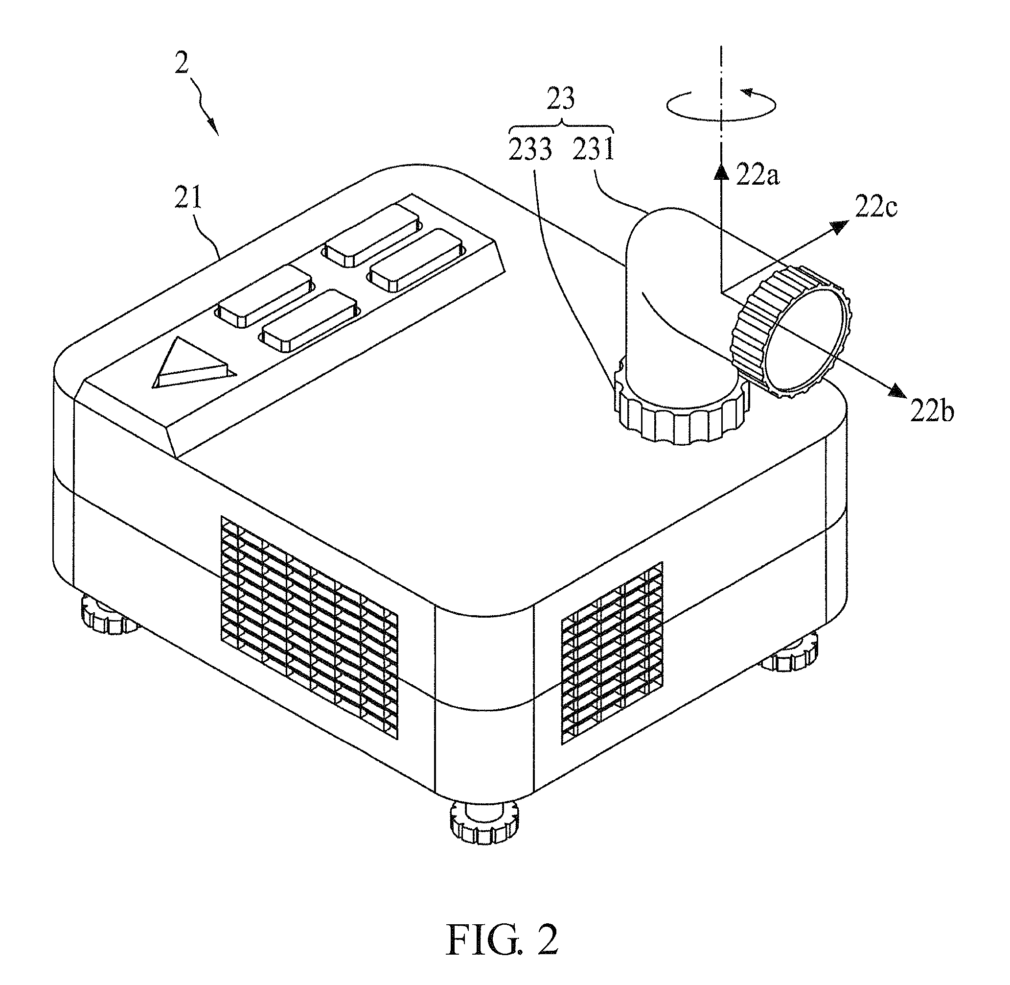
[0023]The first embodiment of this invention is a projection system 2, schematic views of which are shown in FIGS. 2, 3A, 3B and 3C. The projection system 2 comprises a body 21, an imaging module 23, an imaging device 25, and an image outlet (not shown) disposed on the body 21. The projection system 2 is adapted to receive data input from an external digital device (e.g., a television, a computer, a notebook computer, a DVD player or a digital camera). By processing the data, the projection system 2 generates an image (not shown) for projection from the image outlet of the body 21 along a first direction 22a.

[0024]The imaging module 23 comprises an extended lens device 231 and a rotation mechanism 233. The rotation mechanism 233 is disposed between the body 21 and the extended lens device 231 so that the extended lens device 231 is rotatably disposed on the image outlet and connected with the body 21. Thus, the extended lens device 231 is adapted to rotate around the first directio...


PUM


Abstract

The invention provides an imaging module disposed on a projection system. The imaging module comprises an extended lens device, which connects to the image outlet of the body of the projection system by a rotation mechanism. By rotating the rotation mechanism, the projection system may optionally project images through the extending lens device onto the screen in two perpendicular directions, of which the image ratio of the two images are reciprocal.

Description

[0001]This application claims priority to Taiwan Patent Application No. 097135346 filed on Sep. 15, 2008, the disclosure of which is incorporated herein by reference in its entirety.CROSS-REFERENCES TO RELATED APPLICATIONS[0002]Not applicable.BACKGROUND OF THE INVENTION[0003]1. Field of the Invention[0004]The present invention provides an imaging module disposed on a projection system to project an image at an appropriate display ratio.[0005]2. Descriptions of the Related Art[0006]With the advancement of information technology and increase in digital data, digital devices for displaying digital data have also been rapidly developing. For example, projection systems have been created to receive digital data input from an external digital device and project a larger image for easier viewing. In some cases, projection systems may further provide a richer entertainment experience, such as being used to project video games or movie pictures. Thus, projection systems have become popular d...

Claims


Application Information

Patent Timeline
Patent Type & Authority Patents(United States)
IPC IPC(8): H01L27/00
CPCG03B21/14G03B21/28H04N9/3102H04N9/3197G03B21/142
Inventor LIN, HUNG-YING
Owner DELTA ELECTRONICS INC
Learn More