
Concentric knurl ball joint

a technology of concentric knurl and ball joint, which is applied in the direction of mechanical equipment, couplings, transportation and packaging, etc., can solve the problems of disfigured receiving, limited life span of assemblies, and replacement of press-fit type ball joints into control arms, so as to prevent the accumulation of displaced materials, reduce the stress and distortion of the receiving hole, and reduce the effect of dislocation

Active Publication Date: 2016-09-20
TENNECO INC
View PDF22 Cites 7 Cited by
  • Summary
  • Abstract
  • Description
  • Claims
  • Application Information

AI Technical Summary

Benefits of technology

The invention solves problems with previous ball joint assemblies by using a special design that reduces distortion of parts and prevents buildup of material under the stop flange. This design protects the receiving hole in the suspension component and minimizes stress during installation.

Problems solved by technology

Such assemblies have a limited life span and require replacement when indications of wear present.
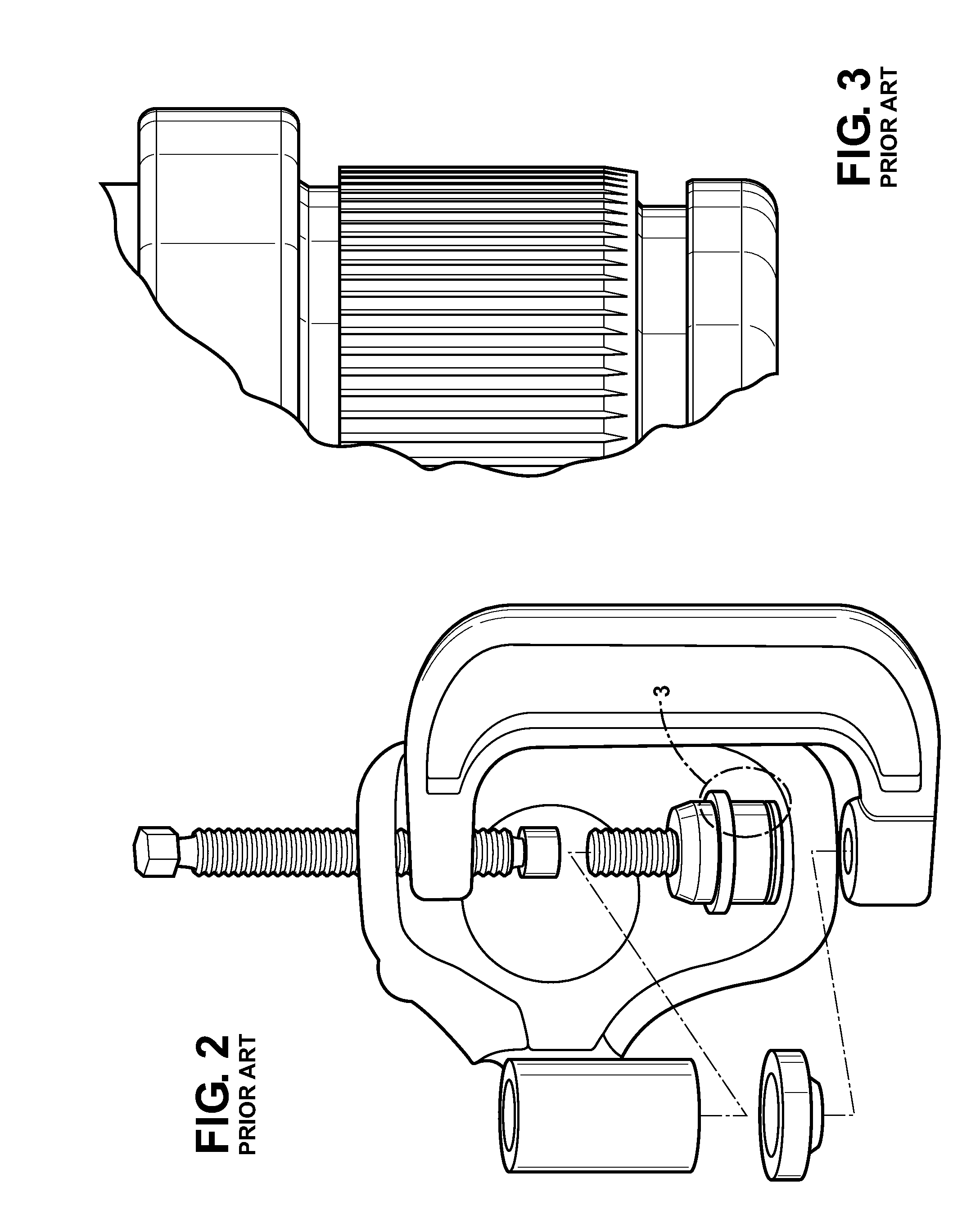
A particular problem experienced by mechanics and others involved in the automobile repair trade involves the replacement of a press-fit type ball joint into a control arm having a worn and / or disfigured receiving hole.
For example, if a particular vehicle has experienced multiple previous ball joint assembly replacement operations, it is likely that the receiving hole in the control arm will have become distorted and enlarged, and possibly also work-hardened by the numerous previous ball joint replacement operations.
As will be appreciated, this can result in increased repair costs, unnecessary waste, and consumer dissatisfaction.

Method used


Image

  • Concentric knurl ball joint
  • Concentric knurl ball joint
  • Concentric knurl ball joint

Examples


Embodiment Construction

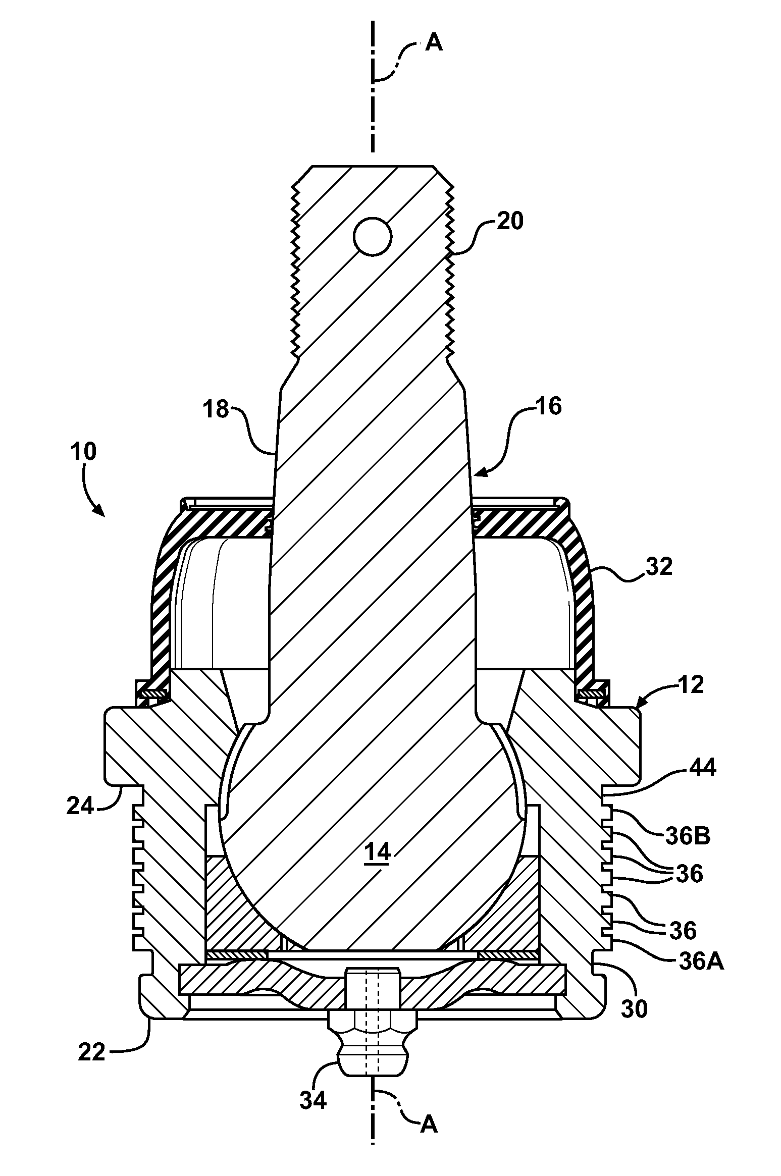
[0022]Referring to the Figures, wherein like numerals indicate like or corresponding parts throughout the several views, a replacement ball joint assembly according to the subject invention is generally shown at 10 in FIG. 4. The assembly 10 includes a cup-like socket housing 12, preferably formed from a metal such as steel, in which is captured the articulating ball head portion 14 of a ball stud 16, also preferably formed from steel or other suitable material. The ball stud 16 includes a mounting shaft 18 that extends integrally away from the ball head portion 14, outwardly from the socket housing 12. The mounting shaft 18 may have a tapered connection surface and a threaded end 20, although the specific shapes and attachment techniques for the mounting shaft 18 may vary from one application to the next.

[0023]The socket housing 12 defines a central axis A, and includes an exterior side wall having a lead-in end 22 and an axially spaced exterior stop flange 24. In practice, the lea...


PUM

PropertyMeasurementUnit
outer diameteraaaaaaaaaa
diameteraaaaaaaaaa
axial widthaaaaaaaaaa

Abstract

A replacement ball joint assembly (10) adapted to be pressed into a previously used and possibly distorted receiving hole (26) in a suspension component such as a control arm (28). A socket housing (12) of the assembly (10) includes a plurality of generally annular, concentric knurls (36) each having a respective crest portion (38) and separated one from another by intervening relief grooves (40). The crest portions (38) of the knurls (36) may be tapered so as to provide a lead-in feature to minimize misalignment during a press-in installation operation. The knurls (36) are preferably softer than the control arm material so that they yield during press-in rather than further disfiguring or enlarging the receiving hole (26). Displaced material from the crest portions (38) of the knurls (36) flows into the relief grooves (40).

Description

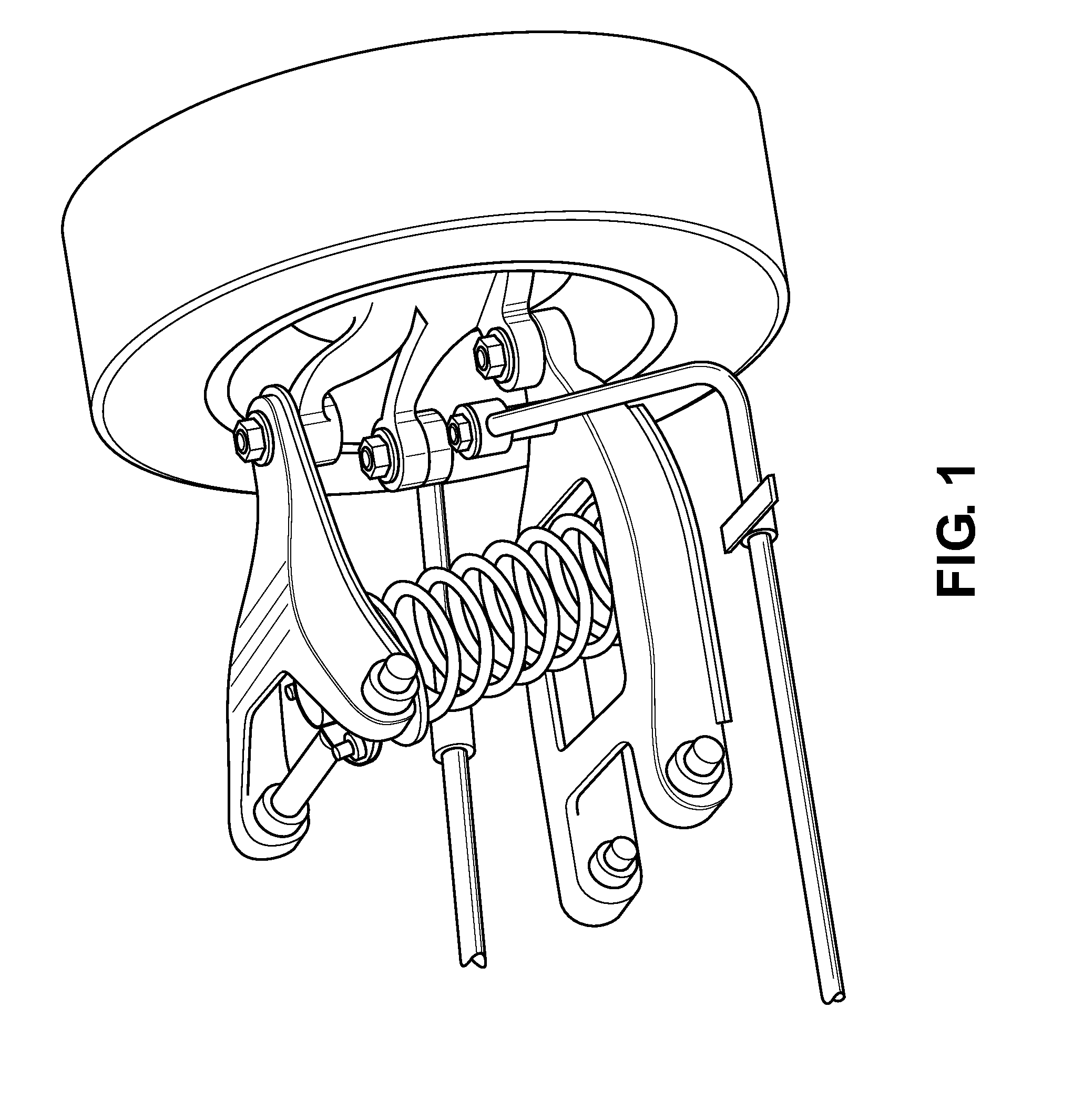
CROSS REFERENCE TO RELATED APPLICATIONS[0001]None.BACKGROUND OF THE INVENTION[0002]1. Field of the Invention[0003]This invention relates to a press-fit type ball joint the type used in automobile and light truck applications, and more particularly toward a replacement ball joint assembly adapted to be pressed into a previously used and possibly distorted receiving hole in a suspension component.[0004]2. Related Art[0005]Suspension systems in many automobiles and light trucks include several ball joint assemblies to provide a pivoting, swiveling connection with the wheels. Ball joints typically comprise spherical bearings connecting upper and / or lower control arms to the respective steering knuckles, like that shown in FIG. 1. Such assemblies have a limited life span and require replacement when indications of wear present. It is not uncommon to replace a ball joint assembly numerous times over the service life of a typical automobile or light truck.[0006]Ball joint assemblies usuall...

Claims


Application Information

Patent Timeline
Patent Type & Authority Patents(United States)
IPC IPC(8): B62D7/16F16C11/06B60G7/00
CPCB60G7/005F16C11/0623B60G2206/82092B60G2206/91Y10T29/4973Y10T403/32631B23P6/00F16C2326/05
Inventor WILCUTT, MICHAELPHILLIPS, GEORGEDAKE, ANTHONYWILLIAMS, RICKIESHORES, CHRISSWAYER, KENNON BRET
Owner TENNECO INC
Learn More