Charge domain filter circuit
a filter circuit and domain technology, applied in the field of charge domain filter circuits, can solve the problems of increasing the amount of electric power consumed, affecting reception, increasing the amount of electric current consumed in the logic circuit, etc., and achieve the effect of low power consumption
- Summary
- Abstract
- Description
- Claims
- Application Information
AI Technical Summary
Benefits of technology
Problems solved by technology
Method used
Image
Examples
first embodiment
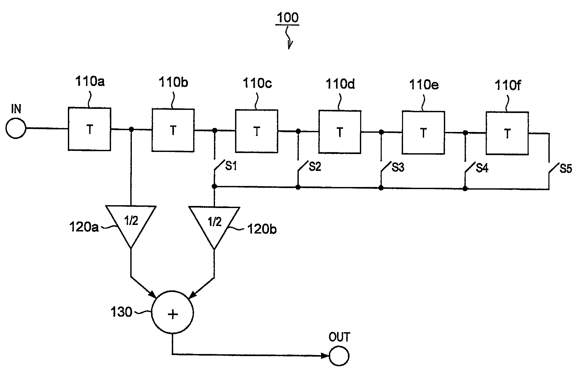
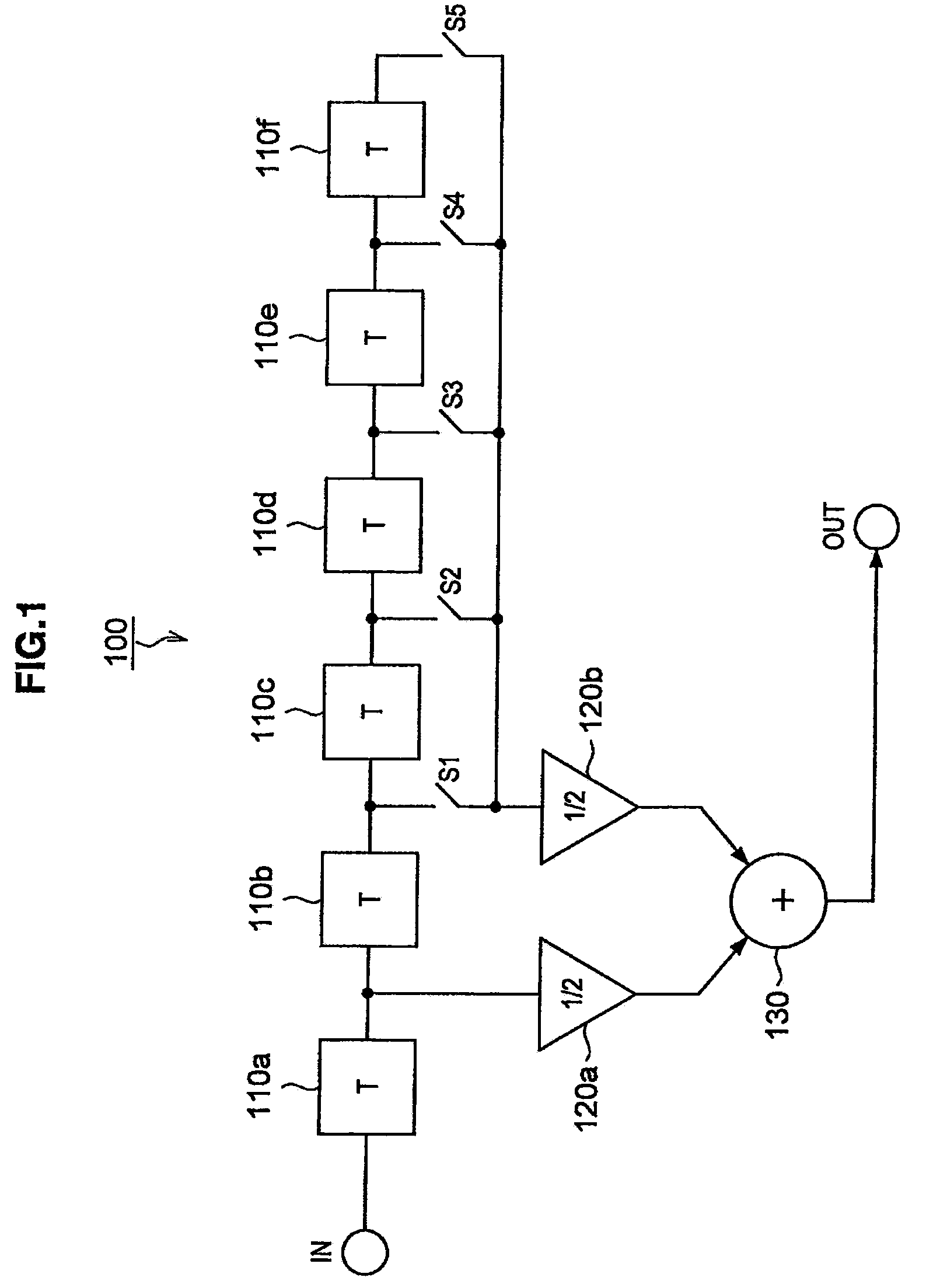
[0045]First, a charge domain filter circuit according to a first embodiment of the present invention will be explained. FIG. 1 is an explanatory figure that uses a block diagram to explain a configuration of a charge domain filter circuit 100 according to the first embodiment of the present invention. The charge domain filter circuit 100 according to the first embodiment of the present invention will be explained below using FIG. 1.
[0046]As shown in FIG. 1, the charge domain filter circuit 100 according to the first embodiment of the present invention is an example of a finite impulse response (FIR) filter and is configured such that it includes delay registers 110a, 110b, 110c, 110d, 110e, 110f, switches S1, S2, S3, S4, S5, multipliers 120a, 120b, and an adder 130.
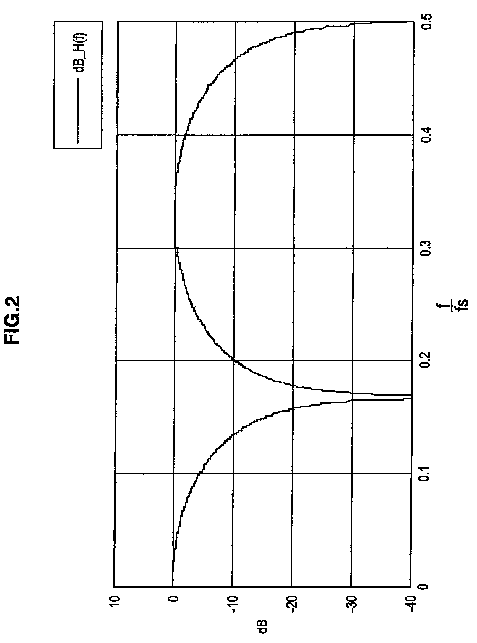
[0047]A discrete-time signal that is sampled from a continuous-time signal at a sampling interval T is input from an input terminal IN to the charge domain filter circuit 100. The sampling frequency is expressed as fs (1 / ...
second embodiment
[0073]The charge domain filter circuit 100 that was explained in the first embodiment of the present invention can change the frequency characteristics by integrating two signals that are sampled at different times and switching the sampling timing of one of the signals. In a second embodiment of the present invention, a charge domain filter circuit will be explained that can change the frequency characteristics by integrating three signals that are sampled at different times.
[0074]FIG. 7 is an explanatory figure that uses a block diagram to explain a configuration of a charge domain filter circuit 200 according to the second embodiment of the present invention. The charge domain filter circuit 200 according to the second embodiment of the present invention will be explained below using FIG. 7.
[0075]As shown in FIG. 7, the charge domain filter circuit 200 according to the second embodiment of the present invention is an example of a FIR filter and is configured such that it includes...
third embodiment
[0110]The charge domain filter circuit 200 that was explained in the second embodiment of the present invention can change the frequency characteristics by integrating three signals that are sampled at different times. In a third embodiment of the present invention, a charge domain filter circuit will be explained that can change the frequency characteristics by integrating four signals that are sampled at different times.
[0111]FIG. 13 is an explanatory figure that uses a block diagram to explain a configuration of a charge domain filter circuit 300 according to the third embodiment of the present invention. The charge domain filter circuit 300 according to the third embodiment of the present invention will be explained below using FIG. 13.
[0112]As shown in FIG. 13, the charge domain filter circuit 300 according to the third embodiment of the present invention is an example of a FIR filter and is configured such that it includes delay registers 310a, 310b, 310c, 310d, multipliers 32...
PUM
 Abstract
Description
Claims
Application Information
 - R&D
- Intellectual Property
- Life Sciences
- Materials
- Tech Scout
- Unparalleled Data Quality
- Higher Quality Content
- 60% Fewer Hallucinations
Browse by: Latest US Patents, China's latest patents, Technical Efficacy Thesaurus, Application Domain, Technology Topic, Popular Technical Reports.
© 2025 PatSnap. All rights reserved.Legal|Privacy policy|Modern Slavery Act Transparency Statement|Sitemap|About US| Contact US: help@patsnap.com


