
Shielding device for optical and/or electronic apparatuses, and space vehicle comprising such device

a technology of optical and/or electronic equipment, applied in the direction of cameras, instruments, nuclear elements, etc., can solve the problems of some drawbacks of shielding devices

Inactive Publication Date: 2011-12-27
THALES ALENIA SPACE ITAL SPA
View PDF14 Cites 10 Cited by
  • Summary
  • Abstract
  • Description
  • Claims
  • Application Information

AI Technical Summary

Benefits of technology

The present invention provides a shielding device for optical and electronic apparatuses that can remove the drawbacks of existing art. The device includes a filter and a support structure that can inflate and unfold to filter electromagnetic radiation. The filter can be positioned transversely when in the active configuration. The invention also includes a space vehicle, such as a satellite, that includes a shielding device for its space telescope. The technical effects of the invention include improved protection of optical and electronic equipment from electromagnetic radiation and improved performance of space telescopes.

Problems solved by technology

However, such shielding devices have some drawbacks.

Method used


Image

  • Shielding device for optical and/or electronic apparatuses, and space vehicle comprising such device
  • Shielding device for optical and/or electronic apparatuses, and space vehicle comprising such device
  • Shielding device for optical and/or electronic apparatuses, and space vehicle comprising such device

Examples


Embodiment Construction

[0020]In the drawings, same or similar elements are indicated by same numeral references.

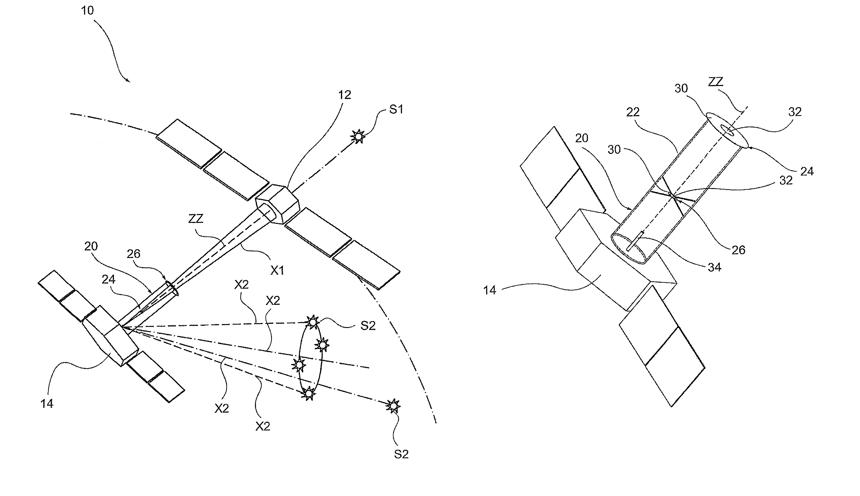
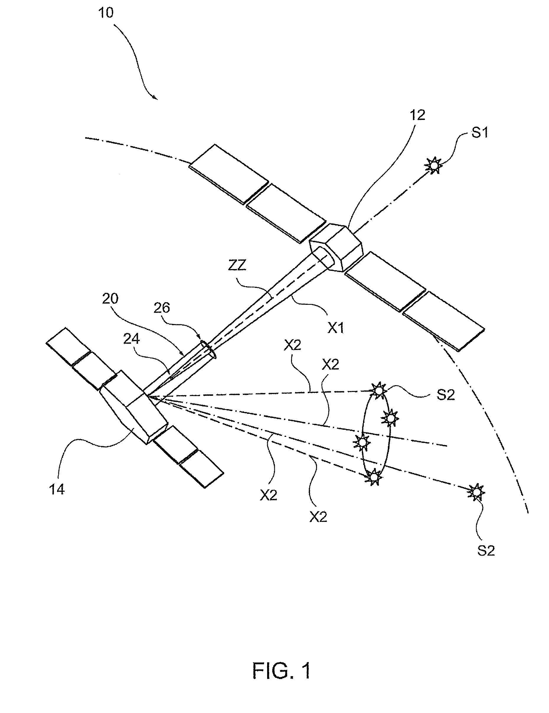
[0021]With reference to FIG. 1, 10 generally indicates a space telescope, in this example, a telescope for observing X-ray sources, including a pair of space vehicles, which may operate in a formation. More in particular, the pair 10 of space vehicles respectively comprises a Mirror Spacecraft 12 or MSC and a Detector Spacecraft 14 or DSC. The MSC carries on board focusing devices and observation optics, such as special mirrors or other types of optics, which are called “mirrors” in the following, and orients them towards the scientific objectives to be observed, such as a celestial body S1. The DSC carries on board an optoelectronic apparatus 16 or detector (schematically shown in FIG. 6), on which images are focused, which may then be processed, stored and / or transmitted to earthbound stations.

[0022]More in particular, in the present example, the detector 16 comprises a plurality of optoelectr...


PUM


Abstract

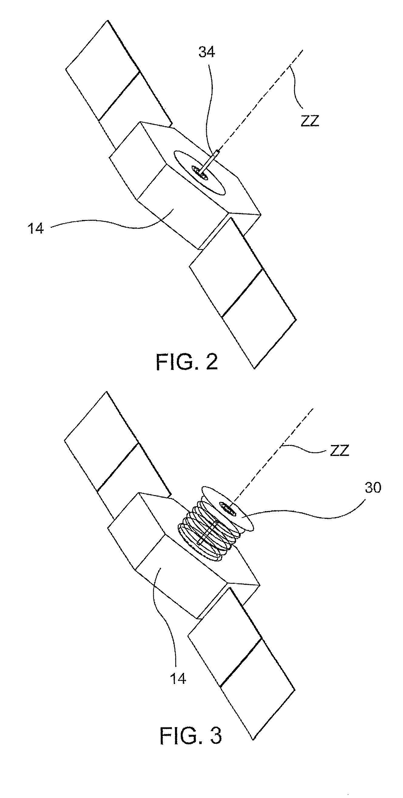
A shielding device (20) for optical and / or electronic apparatuses (16) is described, wherein said apparatuses may cooperate with incident electromagnetic radiation (X1, X2), in particular for space telescopes, the shielding device including:at least a filter (24, 26) provided for interacting with said incident electromagnetic radiation (X1, X2), for selectively filtering said radiation; anda support structure (22) for the filter.The support structure (22) is an inflatable structure, which is able to achieve an operating stand-by configuration, in which it is substantially folded together, and an active operating configuration, in which it extends along the longitudinal extension axis (ZZ), and is essentially completely unfolded. Furthermore, the filter (24, 26) includes a filter body, which is provided in order to be transversely positioned with respect to said longitudinal extension axis, when the support structure reaches its active operating configuration.

Description

CROSS-REFERENCE TO RELATED APPLICATIONS[0001]This application claims priority to foreign European Patent Application EP 08425546.2, filed Aug. 7, 2008, the disclosure of which is incorporated herein by reference in its entirety.FIELD OF THE INVENTION[0002]The present invention relates to a shielding device for optical and / or electronic apparatuses, in particular for space telescopes.BACKGROUND OF THE INVENTION[0003]In the technical field of space applications, there is an urgent need to selectively shield optical and / or electronic apparatuses from undesired electromagnetic radiation, wherein these apparatuses are carried on board of satellites or generally on board of space vehicles.[0004]For example, in the particular field of space telescopes, during observation missions of scientific objectives, more and more often huge telescopes are used, called “Large Telescope”, which are provided on board of satellites. The most recent development of optical telescopes on board of satellites...

Claims


Application Information

Patent Timeline
Patent Type & Authority Patents(United States)
IPC IPC(8): H01J35/16G21K3/00G21K1/02
CPCB64G1/222B64G1/54G02B5/005G02B7/22G02B27/0018G03B11/04B64G2001/224G03B11/00G03B11/045B64G1/2227B64G1/2222
Inventor ATTINA, PRIMOBERTUCCIO, ENRICO DOMENICOBONINO, LUCIANA
Owner THALES ALENIA SPACE ITAL SPA
Learn More