
Collapsible shelters with and without a floating hub

a shelter and hub technology, applied in the direction of buildings, buildings, constructions, etc., can solve the problems of not being easily replaced, not being able to easily replace the tube members of the structure, and not being able to meet the needs of the user,

Active Publication Date: 2011-12-27
HDT EXPEDITIONARY SYST INC
View PDF30 Cites 25 Cited by
  • Summary
  • Abstract
  • Description
  • Claims
  • Application Information

AI Technical Summary

Benefits of technology

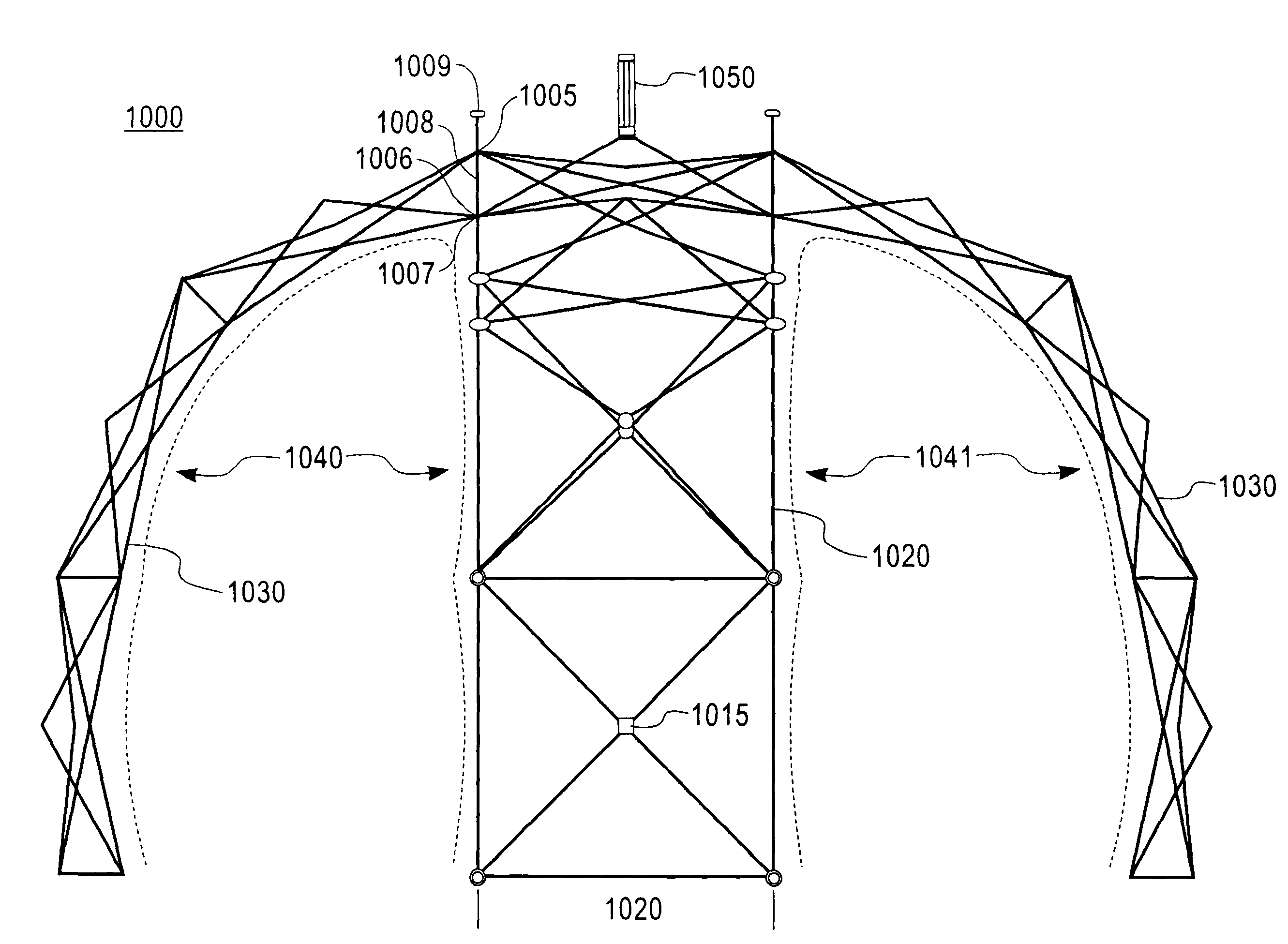
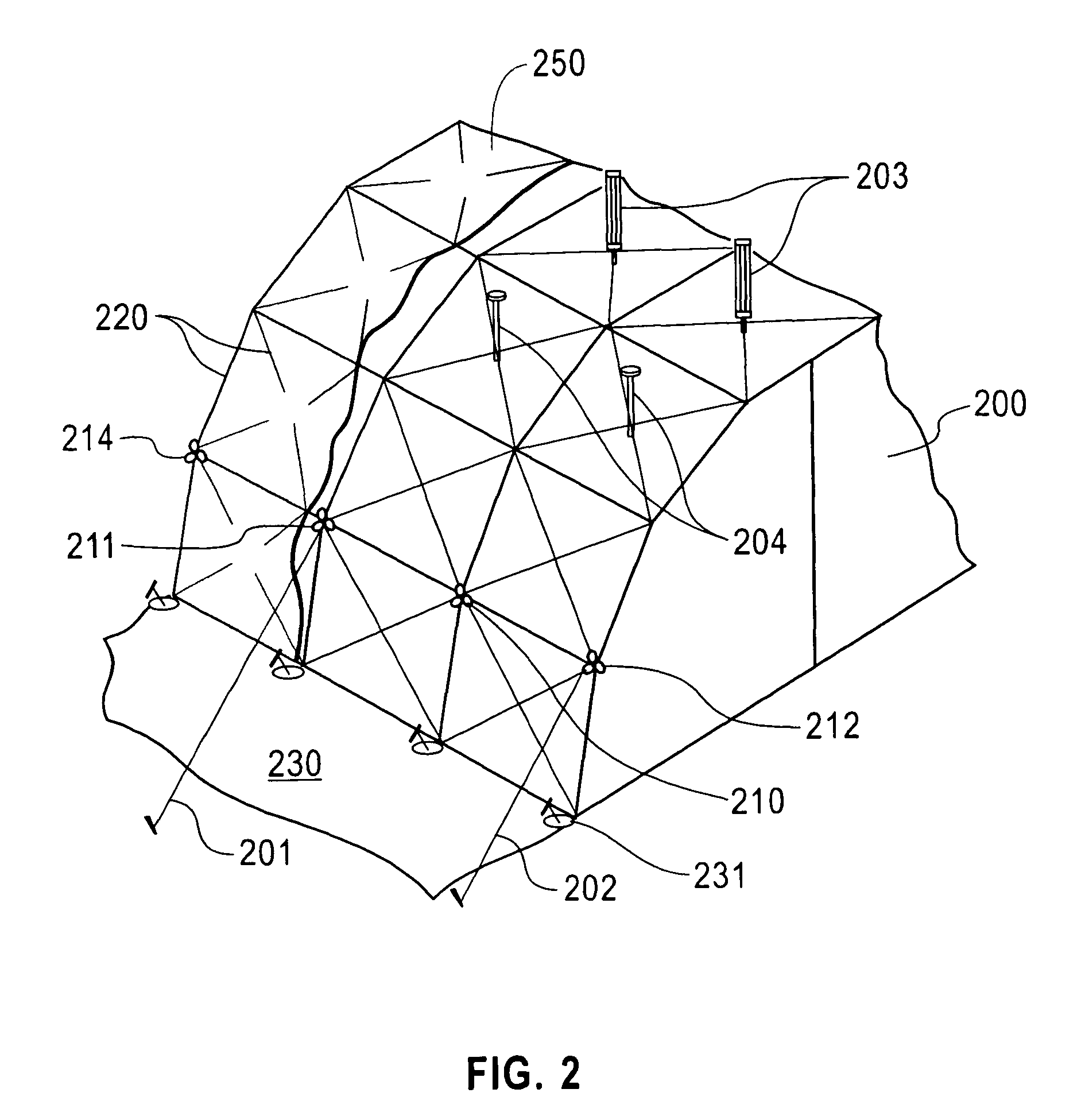
"The present invention is a portable shelter that can be easily assembled and disassembled. It is made up of interconnected quads that create a raised arch when expanded. The shelter has a unique design that allows for flexibility in the interior space desired. The shelter is covered with a flexible material that is held taut by the frame to prevent accumulation of water, ice, and snow. The invention also includes an articulating hub assembly and a floating hub for the exterior cover, which helps to prevent water and snow accumulation and allows for a sharply pitched exterior shape. The floating hub automatically recesses into the frame structure upon striking, reducing tension on the cover and allowing it to fold into the collapsed frame. Overall, the invention provides a portable shelter that is easy to assemble, disassemble, and has improved insulation and protection from weather."

Problems solved by technology

It appears that none of the components is easily interchanged.
The tube members within the structure, therefore, are not easily replaceable since the hub sections cannot be replaced without destroying them.
The prior art large structures disclosed in the references cited above in the past have suffered from a variety of problems.
Some of them are not portable, and some are not collapsible.
Due to the immense size which is needed in many present military and civilian applications, it is often difficult to erect or collapse (i.e., to raise or to lower) the structure network formed from the connecting struts.
The inherent difficulties are that to erect or to collapse a large volume portable structure requires many workers, takes a significant amount of time, and requires special tools and equipment.
The structures are bulky and heavy and have a complicated construction.
However, when attempting to construct a portable building assembly having greater height, width and length dimensions compared with those dimensions disclosed above with respect to the '695 assembly, it was determined that serious problems were encountered with respect to the structural integrity of the shelter.
Using a larger diameter strut with the same size hub as disclosed in the '695 patent will not produce a shelter possessing the required features necessary for prompt tactical deployments.
An increased diameter strut (i.e., greater than ⅝″) used in combination with the prior art hub will not allow the struts to compress when collapsing the structure.
The larger struts result in added structure weight.
In addition to the heavier weight of the structure, there are some substantial construction problems.
This elastic property of the fabric presents a problem when a shelter of large area is erected because at the top of the shelter when the fabric cover is under tension, rain or snow falling on the top surface of the covering fabric (which is initially taut) will tend eventually to weigh down the fabric to the point where it will sag and then will collect the rain or snow in pockets formed as a result.
As more of the rain or snow collects in these pockets, the greater the added weight to the shelter and ultimately, the overall integrity of the shelter is compromised.

Method used


Image

  • Collapsible shelters with and without a floating hub
  • Collapsible shelters with and without a floating hub
  • Collapsible shelters with and without a floating hub

Examples


example 1

[0140]BBABB Refer to FIGS. 17 and 23

[0141]Given: a length L The vertical and horizontal dimension of a strut.

[0142]Given: A full arch BBABB with four B Quads forming four isosceles triangles having an vertex angle of 180° / 4=θ3 and where θ2=θ3 / 2 and θ1+θ2=90° or θ1=(180−θ3) / 2 and connecting at the center with the A Quad.

[0143]Note: There are three center points for this configuration; one for each arch and the center with two different radii. Refer back to FIG. 2.

[0144]Therefore, one side or leg of the isosceles triangle (x+d1) is part of the total width of the shelter W and can be calculated as follows where:

W=L×2(d1)[0145]To find the distance d1, bisect angle θ3 and form a right triangle at the base of the isosceles triangle dividing L into two part: L / 2[0146]Using the Law of Cosines where Cosine θ1=L / 2 / (x+d1) then,

(x+d1)=L / 2 / Cos θ1 [0147]To find the final d1 we need to find x. And the distance x can be calculated from the law of Cosine where Cos θ1=x / L / 2 and x=L / 2 (Cos θ1) and the...

example 2

[0150]BBBBBBB: Refer to FIGS. 17 and 24

[0151]Given: A strut length L

[0152]Given: A full arch with all B Quads: BBBBBBB forming a semi-circle with seven Quads forming seven isosceles triangles each with a vertex angle of 180° / 7=θ3 and θ1=(180−θ3) / 2 and θ2=θ3 / 2

[0153]Note: There is one center point. All seven isosceles triangles legs have the same radius.

W=2(d1)[0154]To find the leg (x+d1), bisect angle Ø3 at the vertex and form a right triangle at the base of the isosceles triangle dividing L into two part: L / 2 and L / 2[0155]Using Law of Cosines where Cos θ1=L / 2 / (x+d1) then[0156]And (x+d1)=L / 2 / Cos θ1 [0157]To find the effective distance (d1) we need to find x. And the distance x can be calculated where Cos θ1=x / L and therefore[0158]x=Cos θ1 (L) and therefore the effective distance (d1) is less x[0159]To calculate the effective height h1, which is less than the radius d1, using the formula:[0160]Sin θ1=h1 / d1 and therefore h1=Sin θ1 / (d1)

example 3

[0161]ABABA: Refer to FIGS. 17 and 25

[0162]Given: A length L

[0163]The procedure to calculate height and width with this Quad configuration is similar to the previous examples. The added height is increased by a factor of L and the added width is increased by a factor of L.

[0164]The quads can be used to create almost any size structure. As depicted in the drawings FIGS. 18 to 25, the basic A and B quads can be connected together in various combinations to create an arch-like structure. Either of the quads can be any size depending upon the length of strut and the ratio of these lengths plus the positioning of the scissor point allowing the struts to articulate.

[0165]The quads, whether A or B comprise a substantially square structure having a base, two sides and a top. They are designated as an “A” quad or a “B” quad depending upon the location of the scissor points along the length of the struts of the subassembly, as explained in greater detail hereinafter. The struts used in a suba...


PUM


Abstract

Collapsible portable self-supporting shelter structures having from at least two component quad sections to seven or more component quad sections, which joined end to end form the width of the structure; and, said entire component sections optionally being joined side to side form a desired depth of the portable shelter. The resulting structure is a collapsible self-supporting prefabricated deployable shelter having a clear span interior without supporting columns.Some versions of the collapsible portable self-supporting shelter structure due to its configuration may optionally contain a floating hub which is a top element extending above the structure's standard exterior matrix frame. The floating hub forms a high pitch atop the shelter, which high pitch causes the fabric, which covers the matrix frame, to be maintained in a taut downward-sloping condition over the shelter top surface so no rain or snow collects in the fabric at the top of the shelter.

Description

[0001]The present invention is a continuation-in-part of U.S. application Ser. No. 11 / 250,340 filed Oct. 14, 2005, now U.S. Pat. No. 7,481,235.FIELD OF THE INVENTION[0002]The present invention relates to a collapsible portable self-supporting shelter structure having at least two component sections forming the walls of said shelter.[0003]The present invention also relates to collapsible, self supporting structures that utilize an improved articulating hub assembly as a connector among tubular rod elements (referred to interchangeably hereinafter as “tubes,”“struts” or “rods”) that in combination, form components designated herein as “quads.” These rod elements, which form the top, bottom and the sides of the quad, are connected to form the structure. The resulting structure is a collapsible self-supporting prefabricated deployable shelter having a clear span interior without supporting columns.[0004]The present invention further relates to a larger version of the collapsible portabl...

Claims


Application Information

Patent Timeline
Patent Type & Authority Patents(United States)
IPC IPC(8): E04H15/44E04B7/10
CPCE04B1/32E04B1/3441E04H15/50
Inventor PRUSMACK, A. JON
Owner HDT EXPEDITIONARY SYST INC
Learn More