
Broadcast receiving device and method of controlling a broadcast receiving device with controller for updating a panel element in a display

ontrol device technology, applied in the control system, control device, controlling method, recording medium and the field of controlling a broadcast receiving device for updating a panel element in the display, can solve the problems of inability of the controller to change the contents of the operation panel, the inability to add new information to the currently displayed operation panel or to make a part of the operation panel not displayed, and the restriction of the provision of a new servi

Inactive Publication Date: 2011-12-20
CANON KK
View PDF16 Cites 11 Cited by
  • Summary
  • Abstract
  • Description
  • Claims
  • Application Information

AI Technical Summary

Benefits of technology

[0023]A fourth aspect of the present invention is a controlling method wherein a controlling device having an operation panel to control a controlled device connected via a network receives data broadcast including operation panel data and changes the operation panel based on the operation panel data.
[0024]A fifth aspect of the present invention is a program to make a controlling device which has an operation panel to control a controlled device connected via a network receive data broadcast including operation panel data and change the operation panel based on the operation panel data.
[0025]A sixth aspect of the present invention is a recording medium to record a program which makes a controlling device having an operation panel to control a controlled device connected via a network receive data broadcast including operation panel data and change the operation panel based on the operation panel data.

Problems solved by technology

However, the above-described controlling system presented a problem such that a controller was not able to change contents of an operation panel.
Therefore, it was impossible to add new information to a currently displayed operation panel or to make a part of the operation panel not displayed.
These imposed restrictions on providing of a new service to a peripheral device in association with the Internet or broadcasting system.

Method used


Image

  • Broadcast receiving device and method of controlling a broadcast receiving device with controller for updating a panel element in a display
  • Broadcast receiving device and method of controlling a broadcast receiving device with controller for updating a panel element in a display
  • Broadcast receiving device and method of controlling a broadcast receiving device with controller for updating a panel element in a display

Examples


first embodiment

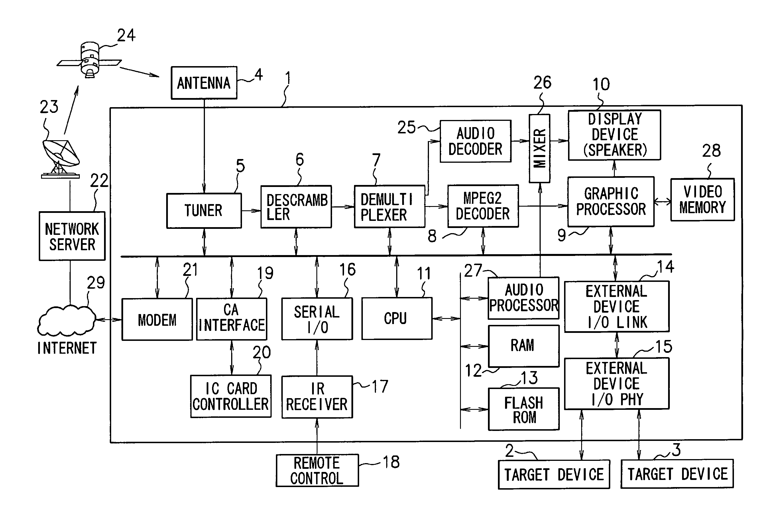
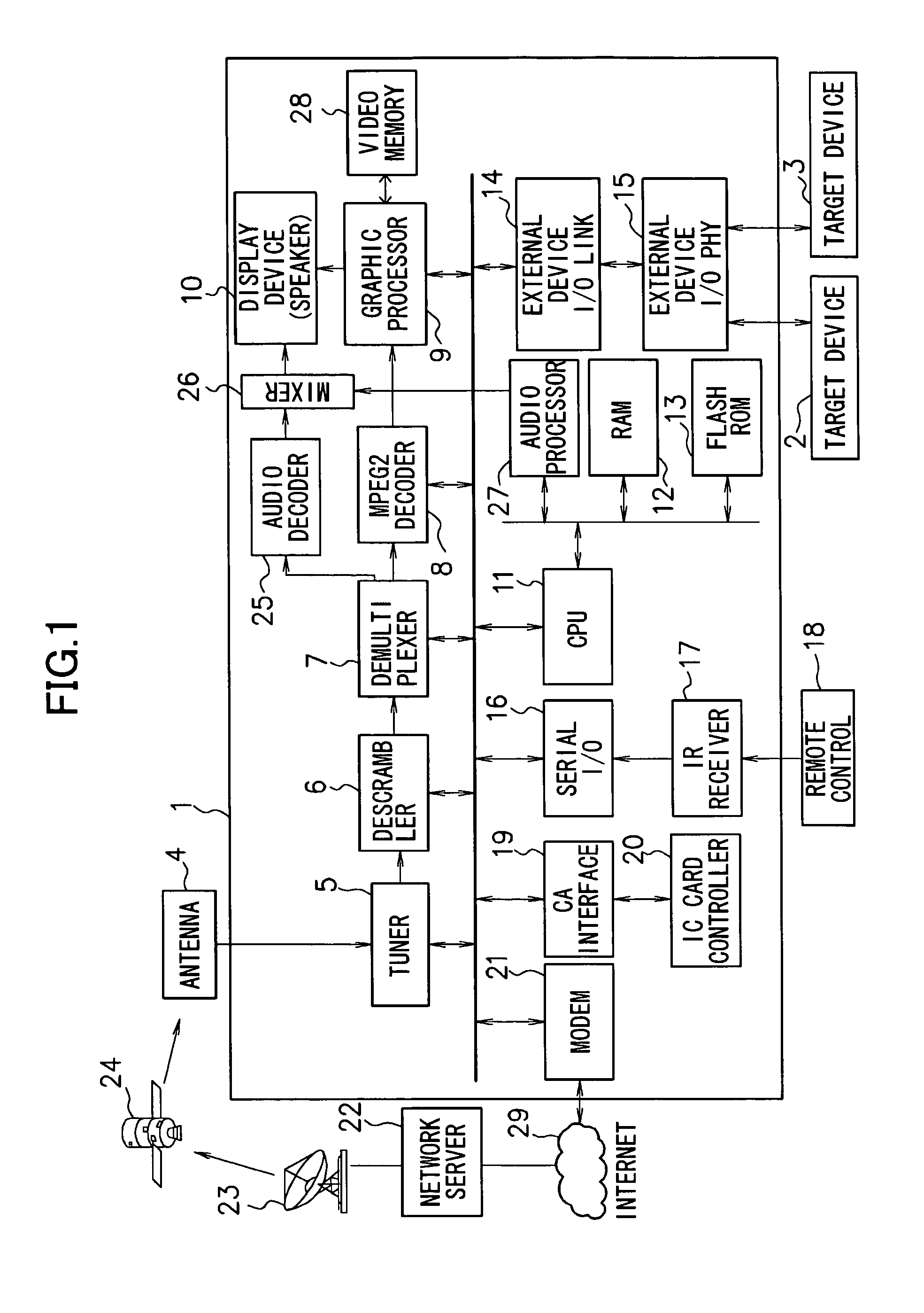
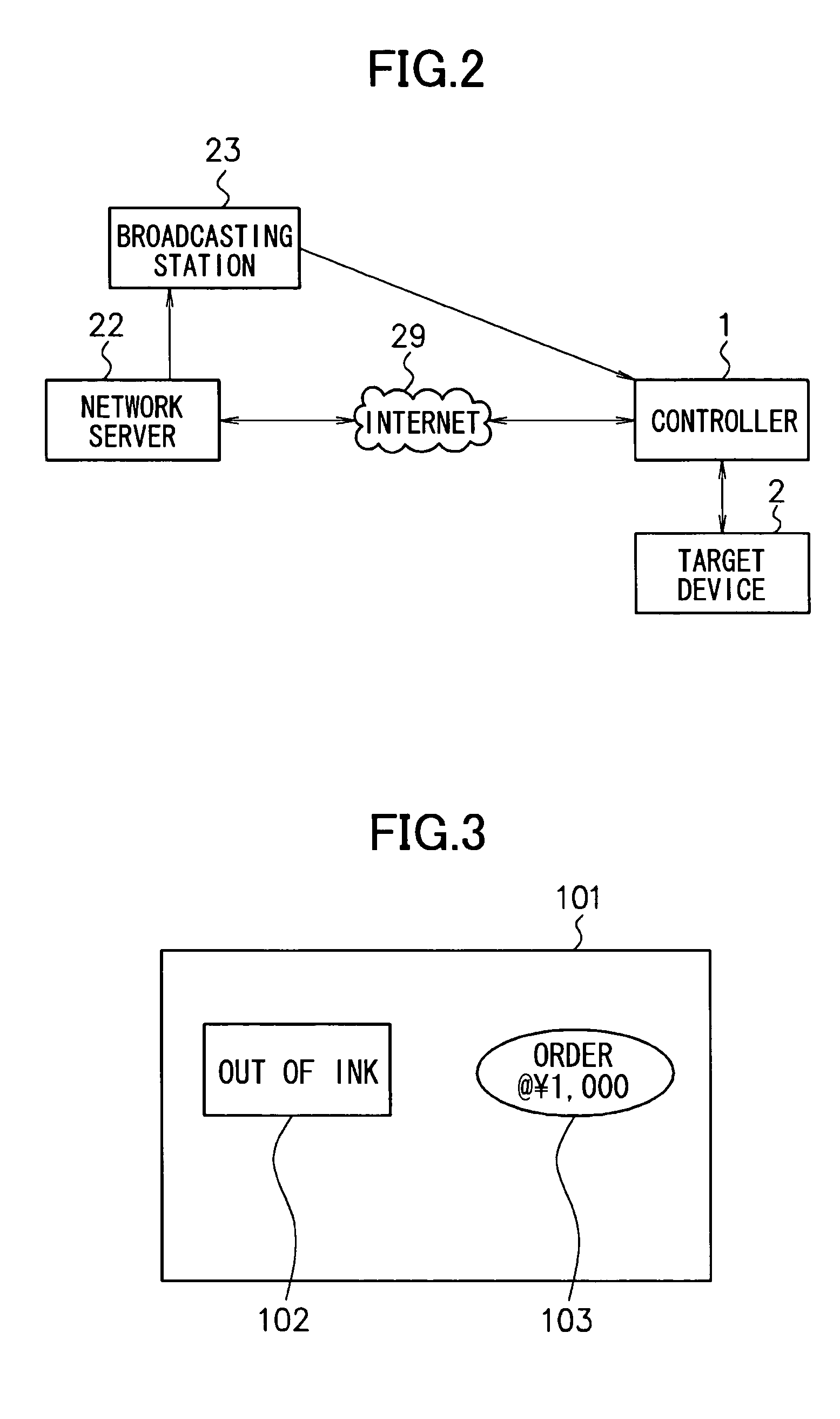
[0061]In the first embodiment described below, the controller 1 in the system shown above in FIG. 1 is a digital television and the target device 2 is a printer. Also in this description of the first embodiment, instead of the operation panel (FIG. 3) based on operation panel data from the target device 2, an operation panel (FIG. 4) based on data broadcast data from the broadcasting station 23 is used to be displayed on the display device 10 of the controller 1.

[0062]The operation panel is a GUI (operation screen) for controlling a target device and displaying a state of the target device, and is particular to (depending on) device type, manufacture and the like of the target device. A general screen of Electronic Program Guide or the like is not included in the operation panel described herein.

[0063]FIGS. 3 and 4 show an example of an operation panel displayed on the display device 10. In the display screen 101 there are disposed panel elements (such as GUI) 102, 103 and 104 consi...

second embodiment

[0114]Next description will be made about the second embodiment.

[0115]The first embodiment has been described above with an example that in the system shown in FIG. 1 above, instead of an operation panel based on an operation panel data transmitted from the target device 2, an operation panel based on data broadcast data from the broadcasting station 23 is used to be displayed on the display device 10.

[0116]In the second embodiment, in the system shown in FIG. 1 above, it is assumed that the controller 1 is a digital television and the target device 2 is a video cassette recorder, an operation panel (FIG. 7) based on operation panel data from the target device 2 is changed to an operation panel (FIG. 8) based on data broadcast data from the broadcasting station 23 based on a logic condition added to the operation panel data and the changed operation panel is displayed at the display device 10.

[0117]FIGS. 7 and 8 show an example of an operation panel to be displayed at the display de...

third embodiment

[0139]Next description will be made about the third embodiment.

[0140]In the above-described first and second embodiments, when an operation panel is displayed on the display device 10, first, operation panel data transmitted from the target device 2 is received. On the other hand, according to the third embodiment, the operation panel data from the target device 2 is not received and data broadcast data transmitted from the broadcasting station 23 is used to display the operation panel shown in FIG. 3 on the display device 10.

[0141]Here in the third embodiment, it is assumed that the controller 1 is a digital television and the target device 2 is a printer.

[0142]Based on a sequence view on FIG. 10, transfer of information regarding an operation panel between the controller 1 and the target device 2 is described.

[0143](1) After turning on the power (switching on), the controller 1 detects the target device 2 connected via the network at the external device I / O physical part 15. Detec...


PUM

PropertyMeasurementUnit
timeaaaaaaaaaa
data transmissionaaaaaaaaaa
poweraaaaaaaaaa

Abstract

A controller (1) and target devices (2, 3) are connected via a network. The controller (1) displays an operation panel for controlling the target device (2) at a display device (10) based on information from the target device (2). The controller (1) is capable of changing an element and a user action of the operation panel based on data obtained by data broadcast.

Description

BACKGROUND OF THE INVENTION[0001]1. Field of the Invention[0002]The present invention relates to a controlling system, a controlling device, a controlling method, a recording medium and a program. Particularly, the present invention is suitably used in a controlling system for remote-controlling operations of a device connected via a network.[0003]2. Description of the Related Art[0004]As one controlling system for a controlling device (hereinafter referred to as “controller”) to remote-control operations of a controlled device (hereinafter referred to as “target device”) via a network, there is conceived a controlling system as described below (for example, see Japanese Patent Application Laid-Open (JP-A) No. 2000-350270 and corresponding U.S. patent application Ser. No. 09 / 579,532).[0005]First, a target device transmits an operation panel, which is stored in advance in a recording medium inside thereof, to a controller via a network. The controller displays the received operation ...

Claims


Application Information

Patent Timeline
Patent Type & Authority Patents(United States)
IPC IPC(8): H04N1/032G06F3/12G06F13/00G11B15/02H04H20/00H04H20/86H04H40/09H04H60/25H04N5/44H04N5/445H04N5/765H04N5/775H04N5/781H04N5/85H04Q9/00
CPCG11B15/023H04N5/44513H04N5/775H04N7/163H04N7/17318H04N21/4104H04N21/4117H04N21/4135H04N21/4312H04N21/4314H04N21/44227H04N21/47815H04N21/488H04N21/8146H04N5/781H04N5/85H04N21/47H04N21/4112
Inventor MIYAMOTO, KATSUHIROYAMAMOTO, TAKASHIOHNO, TOMOYUKI
Owner CANON KK
Learn More