
Autonomous blower for debris herding

a technology of autonomous blowing and debris, which is applied in the direction of turf growing, navigation instruments, instruments, etc., can solve the problems of significantly more problems in the blowing technique of an automated technique than in the field of autonomous blowing of debris herding

Inactive Publication Date: 2011-12-13
BATCHELDER RACHAEL ANNE +1
View PDF7 Cites 7 Cited by
  • Summary
  • Abstract
  • Description
  • Claims
  • Application Information

AI Technical Summary

Benefits of technology

"The present invention is an autonomous blower that moves debris on a surface. It has a chassis with wheels and a blower housing with a motor and a discharge chute. The blower uses GPS to determine its position and a controller to coordinate the movement of the chassis. The controller determines a serpentine trajectory and uses motor-driven louvers to guide the discharge air in different directions. The invention has a teaching mode to create a database of clearable area and target area. The technical effect of the invention is an efficient and effective blower that can move debris on surfaces with minimal human labor."

Problems solved by technology

Organizing people to periodically rake or blow a lawn can be expensive.
However the technique of blowing is significantly more problematic for an automated technique than vacuuming, for at least three reasons.

Method used


Image

  • Autonomous blower for debris herding
  • Autonomous blower for debris herding
  • Autonomous blower for debris herding

Examples


Embodiment Construction

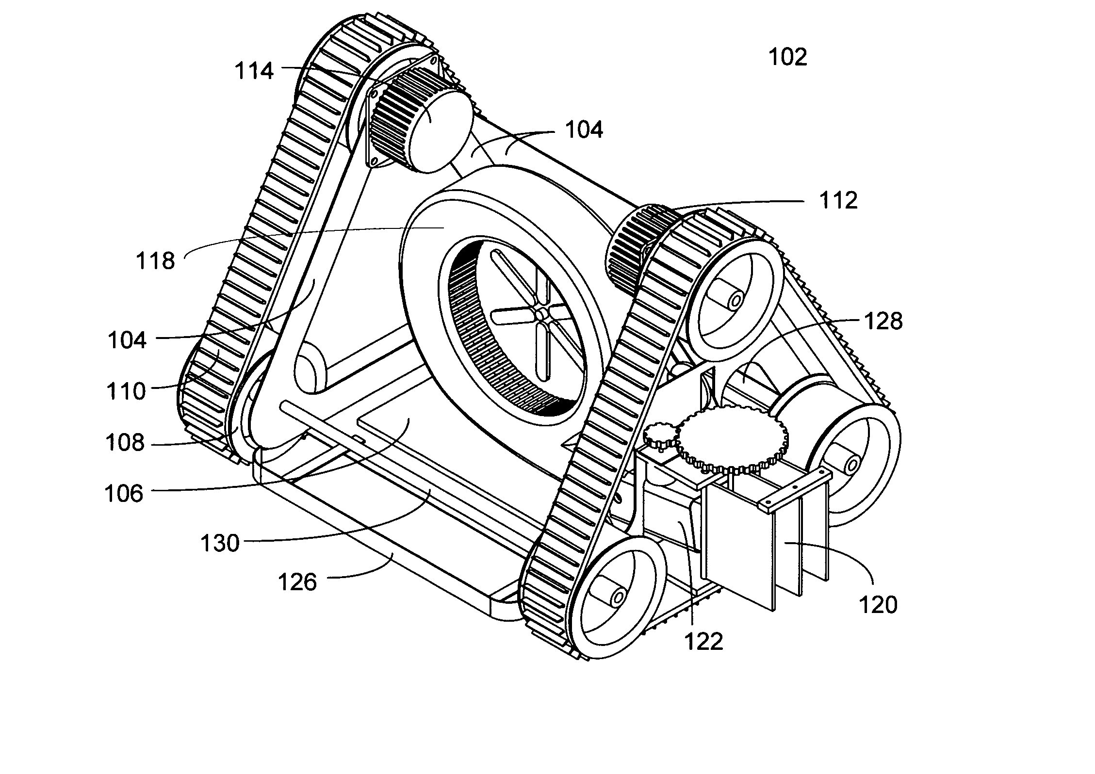
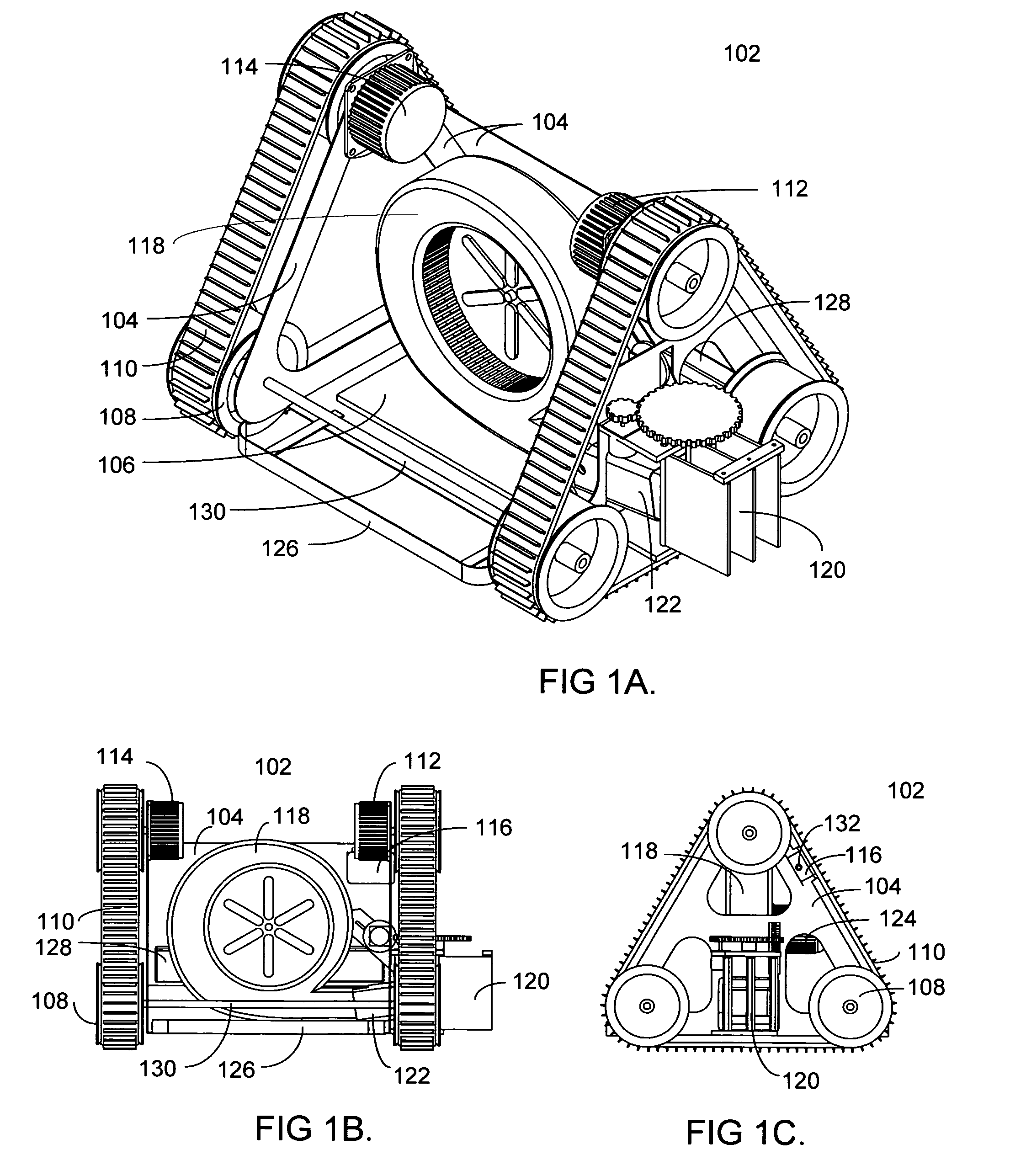
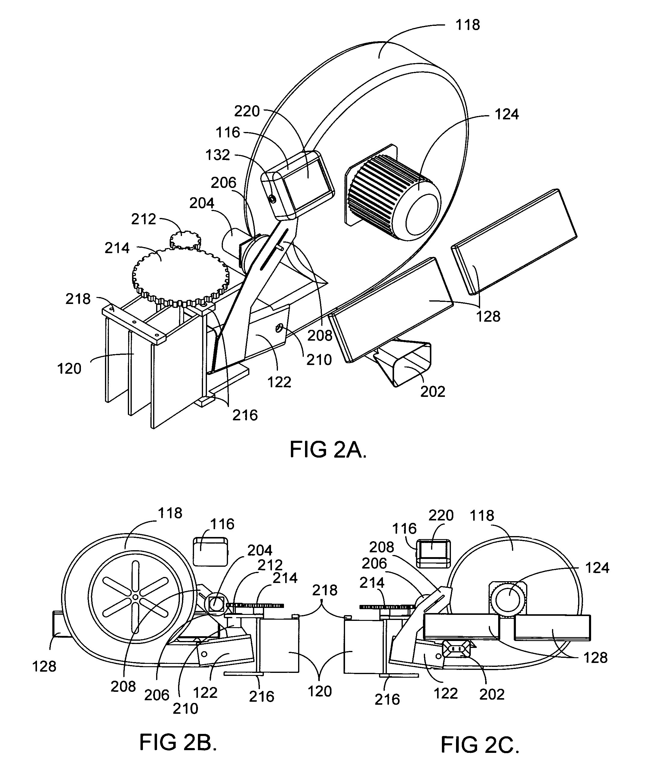
[0019]As shown in FIG. 1A, an autonomous blower (102) comprises a chassis (104) or frame of stamped and welded metal. A counterweight (106) may be incorporated to lower the center of mass, as well as to resist the thrust of the exhausting air. Six wheels (108) on axles (13) are incorporated in this preferred embodiment for moving the chassis about on two independent tracks or belts (110). A first stepper motor (112) drives the front belt, and a second stepper motor (114) drives the rear belt. The symmetric design of this preferred embodiment allows the chassis to move laterally, to spin in place, and to right itself if it flips over. An alternative preferred embodiment has one motor steering a steerable wheel and another motor driving a drive wheel. An alternative preferred embodiment has a first motor driving a first drive wheel, a second motor driving a second drive wheel, and an idler wheel.

[0020]A controller (116) is attached to the chassis (104). The controller comprises prefer...


PUM


Abstract

An autonomous blower is described that utilizes GPS signals for blowing ground debris from a clearable area to a target area. A controller coordinates motors that propel and steer the autonomous blower. A database created in a teaching mode defines clearable, target, and no-trespassing areas with respect to GPS coordinates. An algorithm in the controller computes a serpentine trajectory for the autonomous blower so that it traverses the clearable area while transporting ground debris to the target area.

Description

CROSS-REFERENCE TO RELATED APPLICATIONS[0001]Reference is hereby made to co-pending U.S. patent application Ser. No. 12 / 152,607, filed on May 15, 2008, entitled “Blower and rotary rake for debris herding”, and which published as U.S. Patent Application Publication No. 2009 / 0282795.BACKGROUND OF THE INVENTION[0002]Fallen leaves should be removed from a lawn soon after they fall, both for aesthetics and for the health of the lawn. Delaying their removal allows dew and rain on the fallen leaves to hasten their partial decomposition, which exacerbates their removal. Organizing people to periodically rake or blow a lawn can be expensive.[0003]An automated technique for clearing leaves and other debris from lawns has similarities to robotic lawn mowers, such as described in U.S. Patent Application Publication 2004 / 0133316. There are also analogies to robotic vacuums for cleaning interior floors, exemplified by U.S. Pat. No. 7,024,278 pertaining to the Roomba vacuuming product.[0004]Fallen...

Claims


Application Information

Patent Timeline
Patent Type & Authority Patents(United States)
IPC IPC(8): A47L5/00
CPCA01G1/125E01H1/0809A01G20/47
Inventor BATCHELDER, RACHAEL ANNEBATCHELDER, JOHN SAMUEL
Owner BATCHELDER RACHAEL ANNE
Learn More