Synchronous sampling of PWM waveforms

a waveform and synchronous sampling technology, applied in the field of pulse width modulation, can solve the problems of phase lag, inability to impose a dc or low-frequency waveform directly on a given system, and strict requirements for recovery filters

Active Publication Date: 2011-12-06
DEKA PROD LLP
View PDF19 Cites 9 Cited by
  • Summary
  • Abstract
  • Description
  • Claims
  • Application Information

AI Technical Summary

Benefits of technology

[0012]In one embodiment, a voltage source produces a bus voltage. The PWM waveform is fed to one or more switches that open and close according to the duty cycle of the PWM waveform. When the switch is closed the bus voltage is occurs across the load. This voltage is also presented to the low pass filter. In another embodiment, there is a plurality of loads and a plurality of switches. In such an embodiment a differential signal between the two loads is provided to a differential filter prior to providing a filtered version of the differential signal to the analog to digital converter.

Problems solved by technology

In many cases it is not feasible to impose a DC or low-frequency waveform directly on a given system.
However, as the bandwidth content of the average waveform approaches the carrier frequency, the requirements of the recovery filter become stricter.
One drawback of such a design is phase lag.
The higher the order of the filter, the more accurate the filter is, but the greater the phase lag that is introduced which is undesirable in a feedback control system.

Method used


Image

  • Synchronous sampling of PWM waveforms
  • Synchronous sampling of PWM waveforms
  • Synchronous sampling of PWM waveforms

Examples


Embodiment Construction

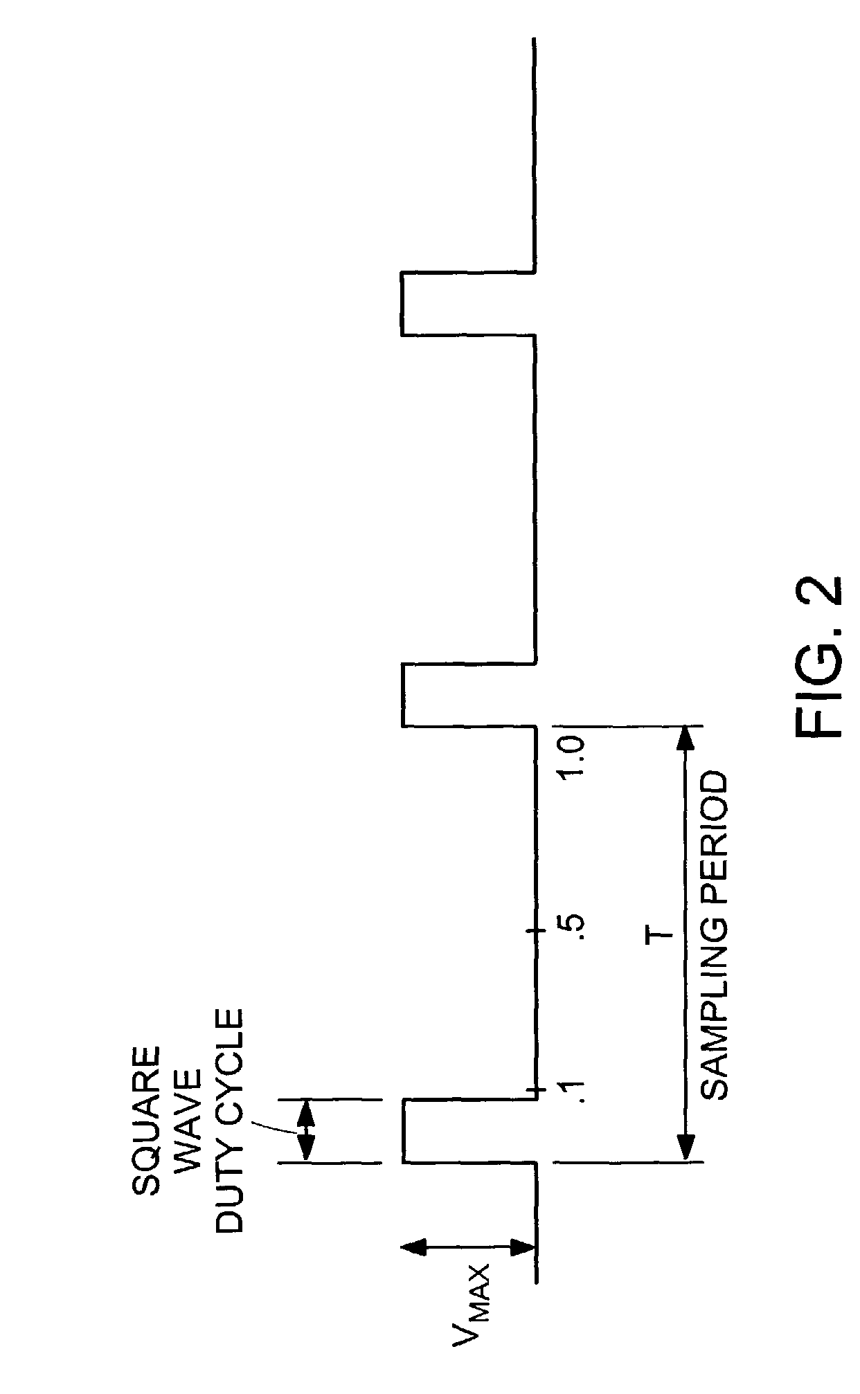
[0036]Definitions. As used in this description and the accompanying claims, the following terms shall have the meanings indicated, unless the context otherwise requires: a “pulse-width modulated waveform” is a digital representation of an analog signal. The “duty cycle” is the fraction of time for which a pulse waveform is at an “on” level. The remainder of the time, the waveform is at an “off” level. The “switching period” is the period of the PWM waveform. For example, FIG. 2 shows a sampling period in which the value that is created is 10% of the input voltage (Vbus). During the sampling period the signal is on for 1 / 10 of the period. Thus, the duty cycle of the pulse is 1 / 10. This waveform produces an average output voltage that is 10% of the voltage of Vbus.

[0037]FIG. 3 is a circuit 300 for filtering a PWM waveform by synchronously resampling the signal. Synchronous resampling is used in order to capture the actual average voltage of the PWM waveform. In FIG. 3, an intended ave...


PUM


Abstract

A device for filtering a carrier frequency of a PWM waveform. The device includes a low-pass filter for converting the PWM waveform into an analog signal. The device further includes a sampling analog-to-digital converter receiving the analog signal from the low-pass filter and the device also includes a controller for causing the non-integrating analog to digital converter to sample the PWM waveform at the pulse frequency rate thereby rejecting the carrier frequency. As already stated the PWM waveform includes a pulse which has a leading edge, a top portion, and a trailing edge. In one embodiment, the controller causes the A/D converter to sample during the top of the pulse. Preferably, the controller causes the A/D converter to sample at substantially the center of the pulse.

Description

TECHNICAL FIELD AND BACKGROUND ART[0001]The present invention relates to pulse width modulation and more specifically to filtering pulse width modulated waveforms.[0002]In many cases it is not feasible to impose a DC or low-frequency waveform directly on a given system. Instead a pulse width modulated (PWM) waveform may be produced and then averaged using a low-pass filter.[0003]It is known in the prior art to use a PWM waveform for producing a high-frequency waveform of a desired average. The analog representation can be recovered by demodulating / filtering the waveform. However, as the bandwidth content of the average waveform approaches the carrier frequency, the requirements of the recovery filter become stricter. The filter must reject the carrier frequency while passing through the desired signal. One means to design such a filter is to create a high order low pass linear time invariant filter. One drawback of such a design is phase lag. The higher the order of the filter, the ...

Claims


Application Information

Patent Timeline
Patent Type & Authority Patents(United States)
IPC IPC(8): H02P27/04H02P25/00
CPCG01R19/2506G01R19/0007H02P21/00H02P27/08
Inventor SACHS, JASON M.HEINZMANN, JOHN DAVID
Owner DEKA PROD LLP
Why Eureka
Try Eureka