Bulk material handling system and control

a technology of material handling and control, applied in the direction of conveyor parts, cleaning, transportation and packaging, etc., can solve the problems of excessive wear, excessive temperature of the scraper blade tip, and wear of the scraper blade during use, so as to prevent the movement of the scraper blad

Active Publication Date: 2011-12-06
MARTIN ENG
View PDF83 Cites 7 Cited by
  • Summary
  • Abstract
  • Description
  • Claims
  • Application Information

AI Technical Summary

Benefits of technology

The damper may dampen movement of the scraping member based upon a control signal generated by the controller. The another damper may dampen movement of the another scraping member based upon another control signal.

Problems solved by technology

The scraping edge of each scraper blade wears during use due to its scraping engagement with the moving conveyor belt.
If the scraper blades are biased against the conveyor belt with an excessive amount of force, this may result in excessive wear to the scraper blades, may cause damage to the conveyor belt, and may cause the tip of the scraper blade to develop an excessively high temperature due to the friction generated between the scraper blade and the moving conveyor belt.
If the scraper blades are biased against the conveyor belt with too small of a force, the scraper blades may not effectively clean the conveyor belt.
In addition, the scraper blades may vibrate or chatter against the conveyor belt, thereby potentially damaging the conveyor belt cleaner and / or the belt, and decreasing cleaning efficiency.
Scraper blade chatter may be caused by unevenness of the conveyor belt, such as sagging of the belt, defects in the belt, or splices in the belt, and by frictional forces generated between the scraper blade and the moving belt.

Method used


Image

  • Bulk material handling system and control
  • Bulk material handling system and control
  • Bulk material handling system and control

Examples


Embodiment Construction

The following description describes techniques of controlling accessories for a bulk material handling system. In the following description, numerous specific details such as logic implementations, opcodes, means to specify operands, resource partitioning / sharing / duplication implementations, types and interrelationships of system components, and logic partitioning / integration choices are set forth in order to provide a more thorough understanding of the present invention. It will be appreciated, however, by one skilled in the art that the invention may be practiced without such specific details. In other instances, control structures, gate level circuits and full software instruction sequences have not been shown in detail in order not to obscure the invention. Those of ordinary skill in the art, with the included descriptions, will be able to implement appropriate functionality without undue experimentation.

References in the specification to “one embodiment”, “an embodiment”, “an e...


PUM


Abstract

A bulk material handling system includes a bulk material handling apparatus to convey bulk material and a bulk material handling accessory to aid the bulk material handling apparatus in conveying the bulk material. The bulk material handling accessory includes a controller having one or more sensors. The controller generates a control signal to adjust operation of the bulk material handling accessory based upon at least one status signal of the one or more sensors. The controller also generates the control signal in accordance with a status signal to control signal response pattern defined by system parameter values. The system parameters include a minimum value to define a minimum level of the control signal associated with fail-safe operation and a maximum value to define a maximum level of the control signal associated with stable operation the bulk material handling accessory.

Description

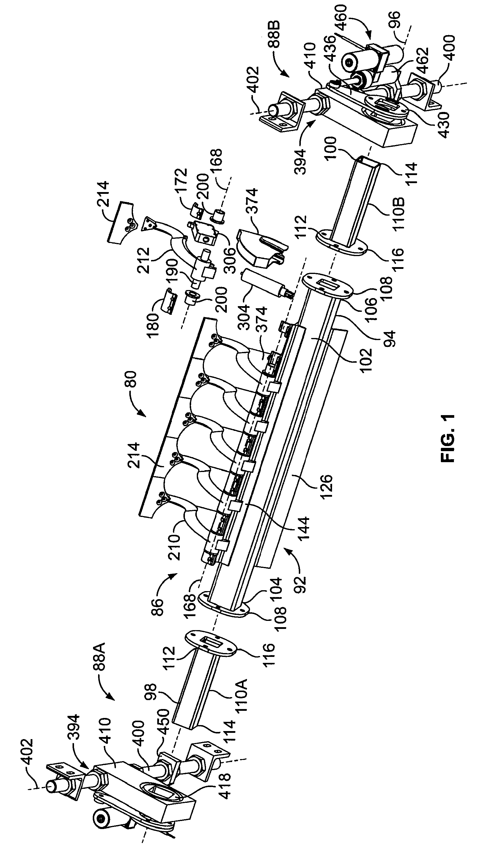
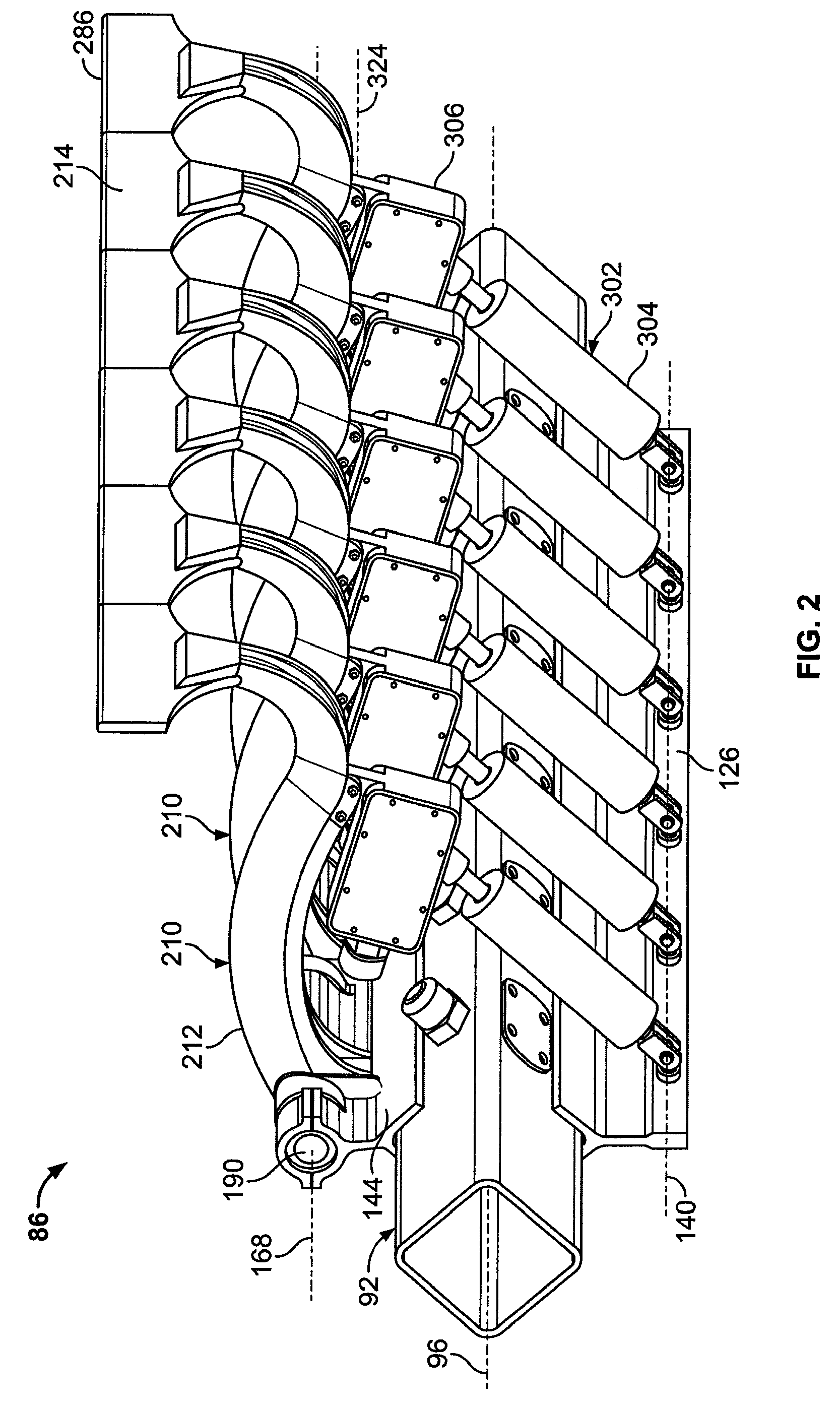
BACKGROUNDBulk material handling apparatus are used in connection with the storage and movement of bulk materials such as grain, sand, gravel, coal and the like. Bulk material handling apparatus include primary apparatus and secondary or accessory apparatus. Primary apparatus include conveyors, conveyor transfer points, transfer chutes, bins, silos, hoppers, associated structures and the like. Accessory apparatus include conveyor belt cleaners, air cannons, industrial vibrators, belt tracking devices and the like that are used in combination with primary bulk material handling apparatus. For example, accessory apparatus such as air cannons and industrial vibrators are used in combination with primary apparatus such as transfer points, transfer chutes, bins, silos and hoppers to facilitate and control the flow of bulk material through the primary apparatus and improve the performance of the primary apparatus. Similarly, secondary apparatus such as conveyor belt cleaners are used in c...

Claims


Application Information

Patent Timeline
Patent Type & Authority Patents(United States)
IPC IPC(8): B65G45/16B65G45/00B65G45/12
CPCB65G45/16
Inventor SWINDERMAN, R. TODDVAVA, CRISTIAN
Owner MARTIN ENG
Why Eureka
Try Eureka