
Method for providing tooth halves with removable tooth tips for an electrical machine

a technology of tooth halves and electrical machines, which is applied in the direction of magnetic circuit rotating parts, magnetic circuit shapes/forms/construction, magnetic bodies, etc., can solve the problems of laborious type of fitting, inability to apply pre-wounding, and more assembly difficulties when assembled, so as to simplify the fitting of linear motors

Inactive Publication Date: 2011-12-06
SIEMENS AG
View PDF12 Cites 13 Cited by
  • Summary
  • Abstract
  • Description
  • Claims
  • Application Information

AI Technical Summary

Benefits of technology

[0007]The object of the invention is to simplify the fitting of a linear motor when using tooth halves with tooth tips.
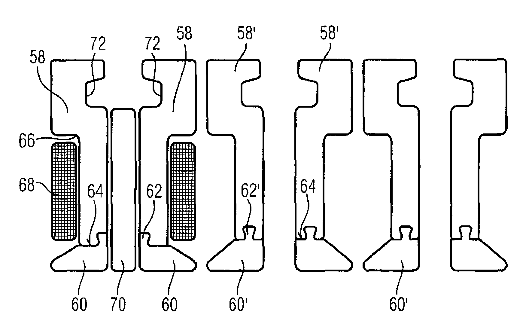
[0009]According to another aspect of the present invention, the object is achieved by a tooth half for a tooth of an electrical machine, in particular a linear motor, with a tooth tip, which has a free end, and on which a desired position for a coil surrounding in each case two identical such tooth halves is defined, wherein the tooth half is shaped in such a way that its thickness from the free end up to the desired position does not exceed the thickness of a desired position, with the result that, when the electrical machine is fitted on two identical such tooth halves, a prewound coil can be pushed on from the free end up to the desired position.
[0011]According to the invention, a plurality of teeth, which each comprise two separate tooth halves with tooth tips, is therefore provided, the tooth halves being shaped or being capable of being modified in such a way that the following steps are made possible: pushing in each case one prewound coil over an open end of the two tooth halves of a tooth up to an end position, and inserting a magnet in each case between the two tooth halves of a tooth. In particular, it is now possible to implement the steps in the described sequence, with the result that the magnets do not need to be inserted until right at the end. The fitting speed is also increased and fitting is overall facilitated by virtue of the fact that the coil can be prewound. This is enabled by the shape or capability of the tooth halves to be modified.
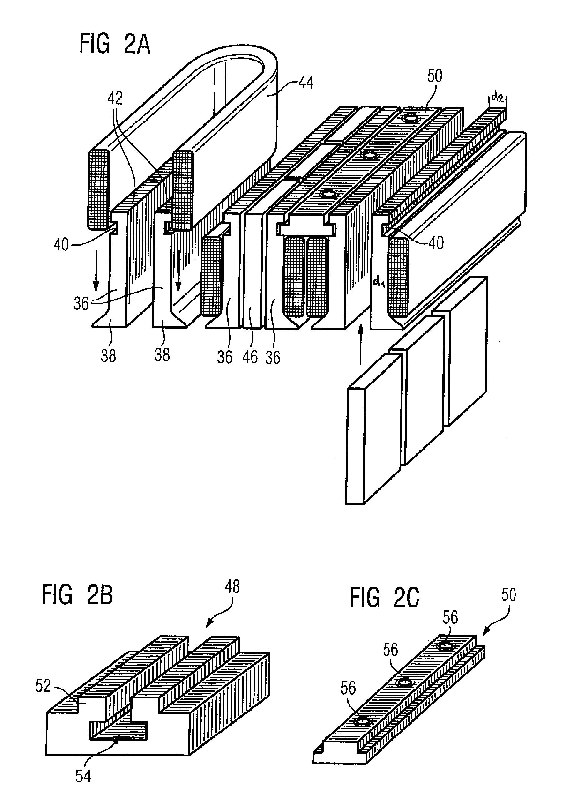
[0016]The separation of the teeth into tooth halves is preferably at least partially counteractive again in the fitted electrical machine. Thus, an embodiment is possible in which in each case two tooth halves of the same tooth are connected to one another via a connecting element (yoke). It is likewise possible, once coils have been pushed on and magnets have been inserted, for in each case adjacent tooth halves, which belong to different teeth, to be connected to one another via a connecting element. In this embodiment, it is preferable for the connecting element to conduct the magnetic flux. A yoke conducting the magnetic flux can comprise, for example, a stack of laminates (by means of the use of baked enamel, which acts as an adhesive once the stack has been baked in an oven). Such a stacked element also makes it possible for threaded bores to be set. Then, it is particularly possible to fix the yoke in the housing of the electrical machine.
[0018]If the yoke is held in slots of the tooth halves and a yoke is used which has been produced by baking laminate parts by means of baked enamel, it is thus possible for threaded bores to be set into the yoke, as a result of which the yoke can be fixed on the housing and then fixing of the tooth halves takes place indirectly via the slot. In this case, the yoke (which can also be referred to as a sliding block in the case of guidance in the slots) absorbs many forces.
[0020]The invention also includes a specially shaped tooth half. This tooth half has a free end, a desired position for a coil surrounding in each case two identical such tooth halves being defined on the tooth half. The tooth half is shaped in such a way that its thickness from the free end up to the desired position does not exceed the thickness at the desired position, with the result that, when the electrical machine is fitted on two identical such tooth halves, a prewound coil can be pushed on from the free end up to the desired position.

Problems solved by technology

In the prior art it is not possible to apply prewound coils onto the tooth halves since the tooth tip is so wide on the tooth tip side that coils are prevented from being plugged on, while the side remote from the tooth tip does not have a free end, with the result that it would be possible for a coil to be plugged on.
This makes assembly more difficult when using tooth halves with tooth tips.
This type of fitting is laborious.
As a result of the permanent magnets being introduced early, component parts can be magnetized, which results in problems during fitting, and may even bring about a risk of injury for the fitter.

Method used


Image

  • Method for providing tooth halves with removable tooth tips for an electrical machine
  • Method for providing tooth halves with removable tooth tips for an electrical machine
  • Method for providing tooth halves with removable tooth tips for an electrical machine

Examples


Embodiment Construction

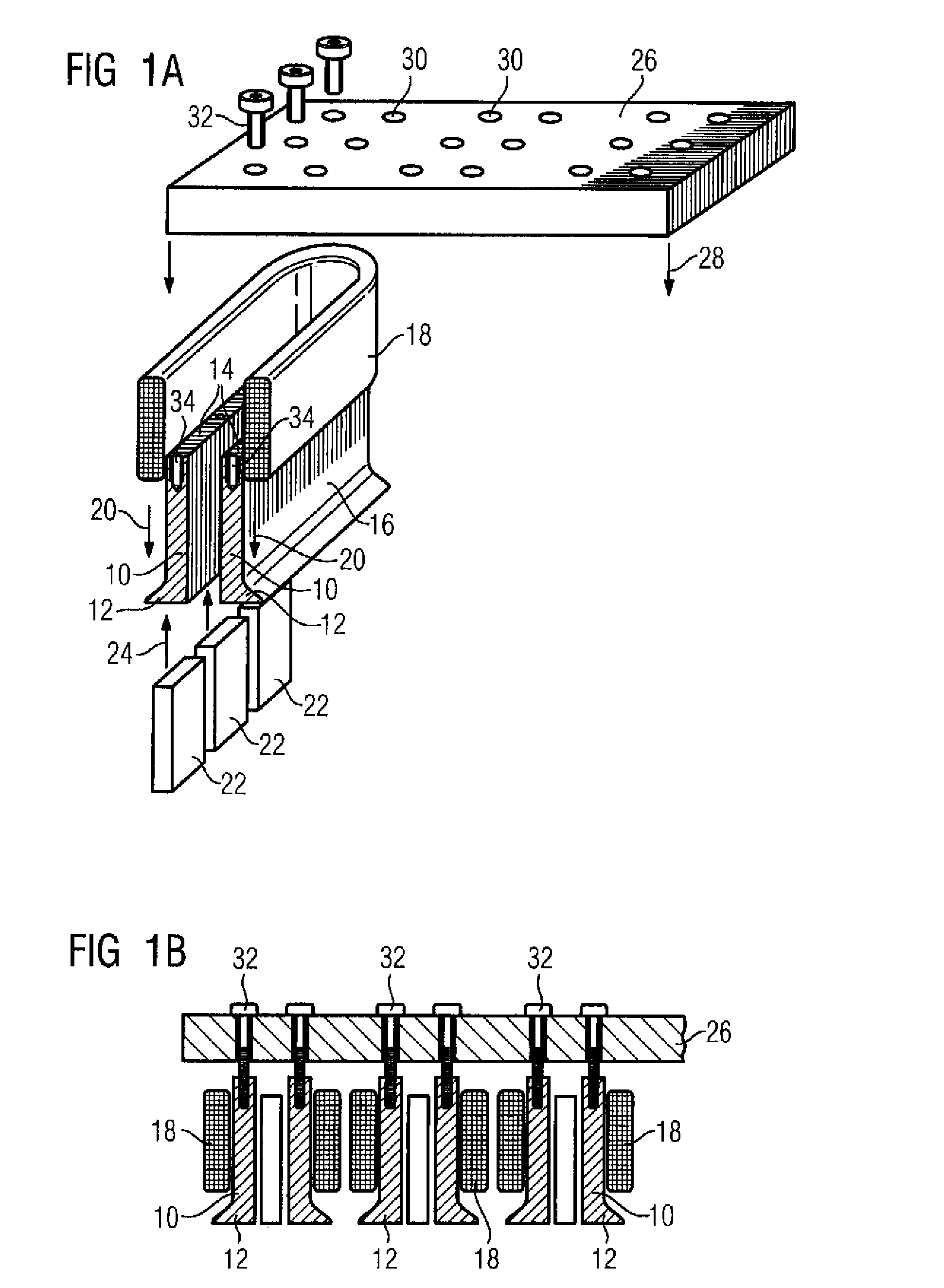
[0029]FIG. 1A shows a tooth, which comprises two tooth halves 10. The tooth halves 10 are substantially plate-shaped, in each case widening of the plate shape occurring at the lower end in FIG. 1A, as a result of which tooth tips 12 are formed. In the assembled state, the tooth tips 12 are located on the side on which the interaction of the primary part with the secondary part takes place.

[0030]Owing to the plate shape of the tooth halves 10, a free end 14 is provided. The plate shape has the same thickness at the free end 14 as in a lower region (still above the tooth tips 12), where a coil is intended to be fitted. As a result of the fact that the tooth halves 10, in contrast to the prior art, for example, do not extend in the region of the free end 14 beyond a plane which is defined by the outer side 16 of the plate, it is now possible for a prewound annular coil 18 (shown in section) to be pushed on corresponding to the arrows 20 until the coil 18 has reached a desired position,...


PUM

PropertyMeasurementUnit
thicknessaaaaaaaaaa
magnetic fluxaaaaaaaaaa
speedaaaaaaaaaa

Abstract

In a method for constructing a linear motor, each tooth of a plurality of teeth is provided with two separate tooth halves with removable tooth tips. After removing the tooth tips to expose an open end of the tooth halves, a prewound coil is pushed over the open end of the two tooth halves of each tooth up to an end position, and a magnet is inserted between the two tooth halves of each tooth. The tooth halves have a thickness between the open end and the end position which does not exceed a thickness of the tooth halves at the end position.

Description

BACKGROUND OF THE INVENTION[0001]The invention relates to a method for constructing an electrical machine, in particular a linear motor. The invention also relates to tooth halves for a tooth of an electrical machine which make it possible to implement the method according to the invention.[0002]In more recent linear motors, both coils and magnets are provided on a primary part (which corresponds to a stator), while the secondary part (which corresponds to the rotor) does not have any separate magnets.[0003]The coils surround in each case two tooth halves, which each have a so-called tooth tip, which is used for guiding the magnetic flux.[0004]In the prior art it is not possible to apply prewound coils onto the tooth halves since the tooth tip is so wide on the tooth tip side that coils are prevented from being plugged on, while the side remote from the tooth tip does not have a free end, with the result that it would be possible for a coil to be plugged on. This makes assembly more...

Claims


Application Information

Patent Timeline
Patent Type & Authority Patents(United States)
IPC IPC(8): H02K15/00
CPCH02K41/033H02K1/148H02K1/223Y10T29/49009Y10T29/49071H02K1/28
Inventor GADELMEIER, MICHAEL-ADOLFMENHART, MICHAEL
Owner SIEMENS AG
Learn More