Exterior mirror vision system for a vehicle

a technology for exterior mirrors and vision systems, which is applied in the direction of television systems, lighting and heating apparatus, lighting support devices, etc., can solve the problem that the pattern generated by the signal light cannot be substantially observed by the driver of the vehicl

Inactive Publication Date: 2011-11-29
MAGNA MIRRORS OF AMERICA INC
View PDF226 Cites 8 Cited by
  • Summary
  • Abstract
  • Description
  • Claims
  • Application Information

AI Technical Summary

Benefits of technology

[0004]The present invention is intended to provide a personal safety feature for a vehicle in the form of a floodlight adapted to projecting light generally downwardly on an area adjacent a portion of the vehicle in order to create a lighted security zone in the area. Advantageously, the floodlight is preferably positioned in the housing of an exterior mirror having a reflective element also positioned in the housing. According to an aspect of the invention, an actuator is provided for the floodlight including a base unit in the vehicle and a remote transmitter. The base unit is responsive to a signal from the remote transmitter in order to actuate the floodlight. This allows the vehicle operator to actuate the floodlight from a distance in order to establish the security zone prior to approaching the vehicle.
[0008]By providing a lighted security zone adjacent the vehicle, users can observe suspicious activity around the vehicle. The pattern of light generated by a security light according to the invention establishes a security zone around, and even under, the vehicle in the important area where the users enter and exit the vehicle. The provision for remote actuation of the security light provides a deterrent to ward off persons lurking around the protected vehicle while the users are still at a safe distance from the vehicle. The provision for a lockout circuit ensures that the security light will not inadvertently be actuated while the vehicle is in motion. The invention, further, conveniently combines a signal light that acts in unison with the vehicle's turn signal, brake light, or both, with the security light in an exterior mirror assembly. The signal light may be designed to be observed by other vehicles passing the equipped vehicle but not directly by the driver of the equipped vehicle.
[0019]In another aspect, the security light is mounted to the non-folding portion of the exterior mirror assembly. In further aspects, the security light includes a housing, a light source positioned to the housing, a light reflecting member supported in the housing, and a cover. The light reflecting member directs light from the light source through the cover. Preferably, the housing is substantially positioned in the non-folding portion of the exterior mirror assembly. Furthermore, the cover is preferably substantially flush with an outer surface of the non-folding portion to reduce the aerodynamic drag of the security light.
[0020]It can be appreciated from the foregoing that the exterior mirror system of the present invention permits an approaching vehicle to observe an actuated signal light without the interference from headlights or brake lights. The exterior mirror system may include a unitary module, which is easily installed or removed for repair, or a signal light assembly which is incorporated into the housing of the mirror assembly.

Problems solved by technology

In this manner, the pattern generated by the signal light cannot be substantially observed by a driver of the vehicle.

Method used


Image

  • Exterior mirror vision system for a vehicle
  • Exterior mirror vision system for a vehicle
  • Exterior mirror vision system for a vehicle

Examples


second embodiment

[0048]FIG. 27 is an elevation view of the exterior rearview minor assembly of the present invention;

[0049]FIG. 28 is a bottom plan view of the exterior rearview minor assembly of FIG. 27;

[0050]FIG. 29 is a plan view of a light module of the exterior rearview mirror assembly of FIG. 28;

third embodiment

[0051]FIG. 30 is a perspective view of the exterior rearview mirror assembly of the present invention;

[0052]FIG. 31 is an exploded perspective view of a signal light of FIG. 30;

[0053]FIG. 31A is a front elevation of a light source of the signal light of FIG. 31;

[0054]FIG. 31B is a side view of the light source of FIG. 31A;

[0055]FIG. 32A is a plan view of a second embodiment of the signal light of FIG. 31;

[0056]FIG. 32B is a plan view of a third embodiment of the signal light of FIG. 31;

fourth embodiment

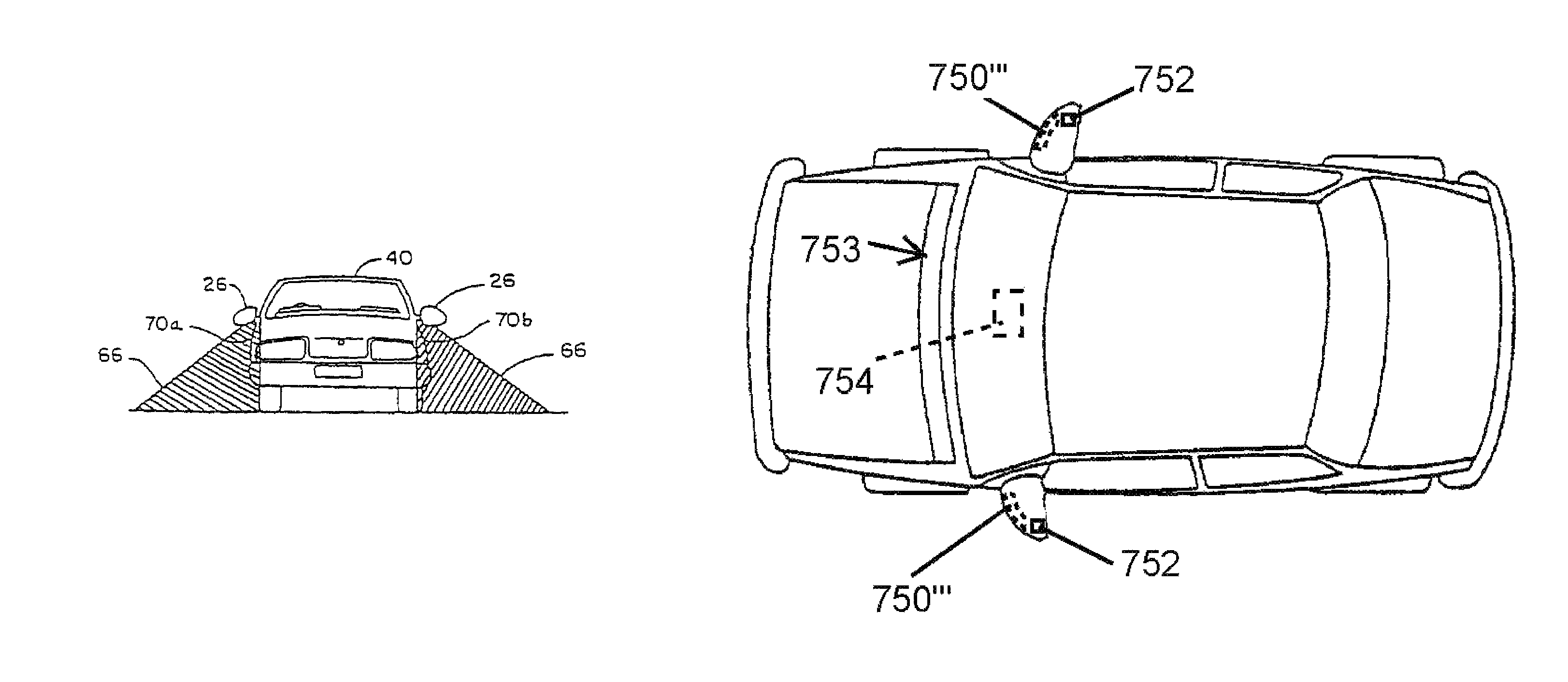
[0057]FIG. 33 is a plan view of the exterior rearview mirror assembly of the present invention shown mounted to a vehicle;

[0058]FIG. 34 is an enlarged plan view of the exterior rearview mirror assembly of FIG. 33 illustrated in a normal extended position;

[0059]FIG. 35 is an enlarged plan view of the exterior mirror assembly of FIG. 33 in a folded position;

[0060]FIG. 36 is a cross-sectional view taken along line XXXVI-XXXVI of FIG. 34 illustrating a light module of the exterior rearview mirror assembly of FIG. 33 and a positioning mechanism for the light module;

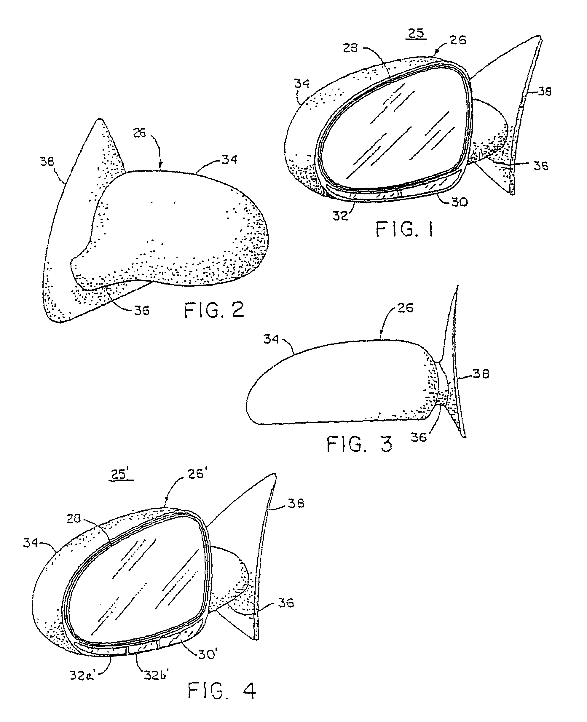
[0061]FIG. 37 is an elevation view of one the exterior rearview mirror assemblies of FIG. 33;


PUM


Abstract

An exterior mirror vision system includes a driver-side exterior rearview mirror assembly mounted at a driver side of an equipped vehicle and a passenger-side exterior rearview mirror assembly mounted at a passenger side of the equipped vehicle. The driver-side exterior mirror assembly including a mounting portion configured for mounting at the driver side of the equipped vehicle, a driver-side exterior mirror housing, and a driver-side reflective element. The driver-side exterior rearview mirror assembly includes a driver-side light module and a driver-side camera. The passenger-side exterior mirror assembly includes a mounting portion configured for mounting at the passenger side of the equipped vehicle, a passenger-side exterior mirror housing, and a passenger-side reflective element. The passenger-side exterior rearview mirror assembly includes a passenger-side light module and a passenger-side camera. The driver-side camera and the passenger-side camera are part of a multi-camera vision system of the equipped vehicle.

Description

CROSS REFERENCE TO RELATED APPLICATIONS[0001]This application is a continuation of U.S. patent application Ser. No. 12 / 632,213, filed Dec. 7, 2009, now U.S. Pat. No. 7,850,351, which is a continuation of U.S. patent application Ser. No. 11 / 495,050, filed Jul. 28, 2006, abandoned, which is a continuation of U.S. patent application Ser. No. 10 / 770,097, filed Feb. 2, 2004, now U.S. Pat. No. 7,083,312, which is a continuation of U.S. patent application Ser. No. 10 / 190,840, filed Jul. 8, 2002, now U.S. Pat. No. 6,685,348, which is a continuation of U.S. patent application Ser. No. 09 / 866,398, filed May 25, 2001, now U.S. Pat. No. 6,416,208, which is a continuation application of U.S. patent application Ser. No. 09 / 335,010, filed Jun. 17, 1999, now U.S. Pat. No. 6,276,821, all of which are incorporated by reference herein in their entireties.TECHNICAL FIELD AND BACKGROUND OF THE INVENTION[0002]This invention relates generally to security systems for vehicles and, more particularly, to rem...

Claims


Application Information

Patent Timeline
Patent Type & Authority Patents(United States)
IPC IPC(8): B60Q1/26
CPCB60Q1/2665B60Q1/48B60R1/12H04N7/181B60Q1/52B60R1/006B60R1/04B60Q2400/40B60R1/1207B60R2001/1284B60R2001/1253
Inventor PASTRICK, TODD W.VAN DE VEN, MICHIEL P.WHITEHEAD, PETER J.MOUSSEAU, RICKLYNAM, NIALL R.
Owner MAGNA MIRRORS OF AMERICA INC
Why Eureka
Try Eureka