
Orthodontic flossing implement

a flossing implement and orthodontic technology, applied in the field of dental hygiene devices, can solve the problems of insufficient strength of prior art flossing devices, inability to easily cut through the tight contacts of adjacent teeth, and inability to comfortably hold and/or access the posterior molar clearances of the upper and lower arches, etc., to achieve quick and easy operation and encourage patient daily flossing complian

Inactive Publication Date: 2011-11-22
ALLEN MARGARITA B
View PDF13 Cites 8 Cited by
  • Summary
  • Abstract
  • Description
  • Claims
  • Application Information

AI Technical Summary

Benefits of technology

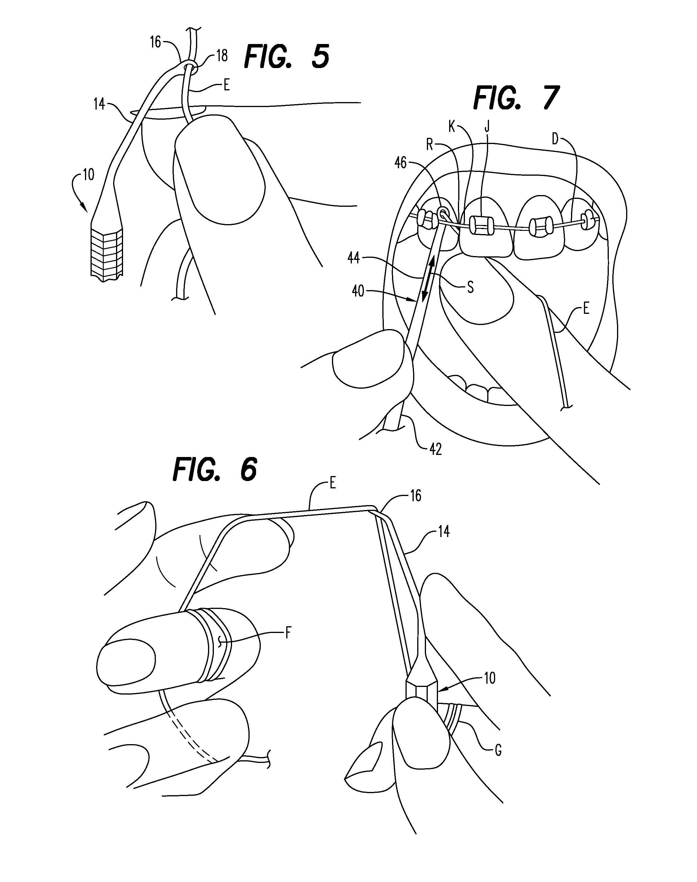
[0018]This invention is directed to an orthodontic flossing implement for facilitating positioning and manipulating of a portion of a length of dental floss through the contact and into the interdental space between adjacent teeth and proximate to an orthodontic wire which defines an arch (clearance) extending between adjacent orthodontic brackets on the teeth. An elongated handle dependently supports an elongated, slender shaft formed as a unit with, and extending from a proximal end of the handle. The shaft is dimensionally smaller in thickness than that of said handle and preferably oriented at an acute angle to the handle. A tip, formed as a unit with, and extending from a second end of the shaft, is oriented at an acute angle to the handle, the tip having an aperture formed therethrough sized to just receive a length of dental floss. The tip with the dental floss positioned through said aperture, is manipulable by said handle to pass beneath an arch of the orthodontic wire and to floss the interdental tissues at all 26 possible arches (clearances) continuously and quickly with ease, thus encouraging patient daily flossing compliance as prescribed by their dental professional.
[0019]It is therefore an object of this invention to provide an improved orthodontic flossing implement for maintaining healthy interdental tissues between adjacent teeth of a person wearing orthodontic braces.
[0020]Still another object of this invention is to provide an orthodontic flossing implement having improved structural features which greatly facilitate the maintaining of healthy interdental tissue of an orthodontic brace-wearing patient.
[0021]Yet another object of this invention is to provide an orthodontic flossing implement which will enable patients undergoing permanent orthodontic treatment easy and quick daily flossing routines for all twenty-six (26) possible intradental space tissue sites.
[0022]And another object of this invention is to provide an orthodontic flossing implement which will enable patients whose oral anatomy makes it difficult to access the posterior and retromolar areas comfortably and with ease.

Problems solved by technology

Prior art devices require a great amount of time, dexterity, and effort to reach the posterior clearances of the upper and lower arches.
These flossing devices are either too small to comfortably hold and / or too small to access the posterior molar clearances or too big to fit between the inter-proximal space of adjacent teeth and / or to fit under the arch wire of the appliance at the clearance.
Prior art devices also are not strong enough to easily cut through the tight contacts of adjacent teeth or to properly remove the bacterial plaque from the interproximal surface of the teeth and gums at the arch (clearance).
With some prior art devices, patient compliance to daily flossing is near impossible, rendering the patient susceptible to bacterial plaque damaging effects to the gums, teeth and the surrounding jawbones.
This plastic needle-like design with an opening for the floss is very inconvenient and time consuming to use.
Accessibility of posterior clearances is difficult and the small floss threader has to be threaded through each and all possible (arch sites) clearances.
This hook member catches on the arch wire and makes this device tedious to use.
Other limitations of the related art will become apparent to those skilled in the art upon a reading of the specification and a study of the drawings.

Method used


Image

  • Orthodontic flossing implement
  • Orthodontic flossing implement
  • Orthodontic flossing implement

Examples


Embodiment Construction

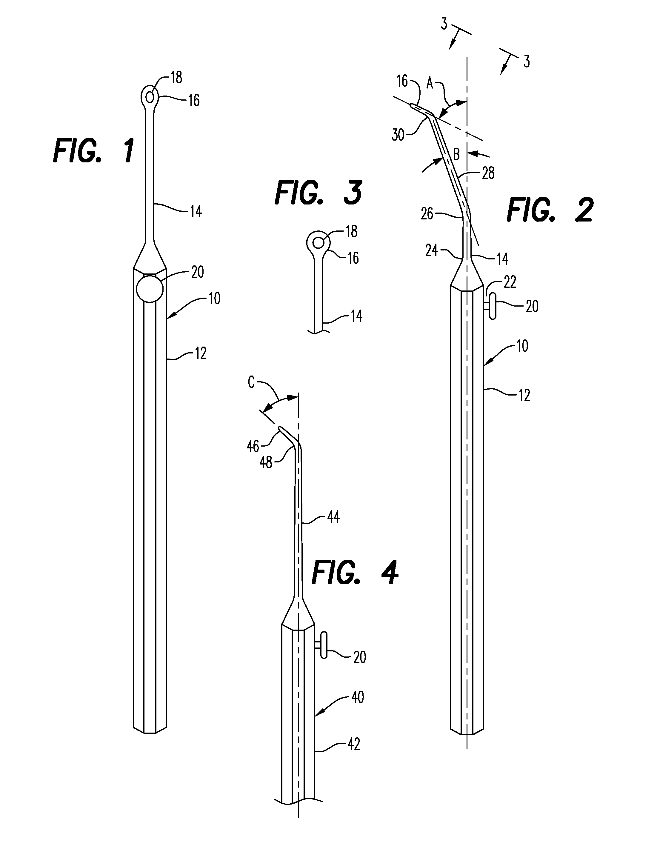
[0036]Referring now to the drawings, and firstly to FIGS. 1 to 3, the preferred embodiment of the invention is there shown generally at numeral 10. This orthodontic flossing implement 10 is preferably formed of surgical steel which may be autoclaved for repeated use in a professional practice by a dental practitioner on a patient and for personal oral hygiene at home. An elongated handle 12 preferably textured for secure grasping and better manipulation (not shown) is formed as an elongated octagonal shape dimensionally narrowing into a shaft 14 which, in front elevation, is substantially straight as shown in FIG. 1.

[0037]However, in FIG. 2, the shaft 14 includes a bend 26 between shaft portions 24 and 28 defining an acute angle B between the longitudinal axis of the handle 12 and the main portion of the shaft 14.

[0038]Disposed at the upper or distal end of the shaft 14 is a generally flat circular tip 16 which is oriented to the shaft about bend 30 so as to define another acute ang...


PUM


Abstract

An orthodontic flossing implement for facilitating positioning and manipulating of a portion of a length of dental floss into the interdental space between adjacent teeth and proximate to and beneath an orthodontic wire which defines an arch extending between adjacent orthodontic brackets on the teeth. An elongated handle dependently supports an elongated, slender shaft formed as a unit with, and extending from a proximal end of the handle. The shaft is dimensionally smaller in thickness than that of said handle and preferably oriented at an acute angle to the handle. A tip, formed as a unit with, and extending from a second end of the shaft, is oriented at an acute angle to the handle, the tip having an aperture formed therethrough sized to just receive a length of dental floss. The tip with the dental floss positioned through said aperture, is manipulable by said handle to pass beneath an arch of the orthodontic wire and to floss the interdental tissue.

Description

CROSS-REFERENCE TO RELATED APPLICATIONS[0001]Not applicableSTATEMENT REGARDING FEDERALLY SPONSORED RESEARCH OR DEVELOPMENT[0002]Not applicableINCORPORATION-BY-REFERENCE OF MATERIAL SUBMITTED ON A COMPACT DISC[0003]Not applicableBACKGROUND OF THE INVENTION[0004]1. Field of the Invention[0005]This invention relates generally to dental hygiene devices, and more specifically to an orthodontic flossing implement and method of use thereof, wherein the present invention facilitates thorough inter-dental flossing of orthodontically-treated teeth and, in particular, teeth fitted with braces.[0006]2. Description of Related Art[0007]In a majority of the cases, persons requiring orthodontic treatment including orthodontic appliances in the form of fixed braces are children, pre-teens and teenagers. Prior art devices require a great amount of time, dexterity, and effort to reach the posterior clearances of the upper and lower arches. These flossing devices are either too small to comfortably hol...

Claims


Application Information

Patent Timeline
Patent Type & Authority Patents(United States)
IPC IPC(8): A61C15/00
CPCA61C15/045
Inventor ALLEN, MARGARITA B.
Owner ALLEN MARGARITA B
Learn More