
Dual-action single-key mechanism

a single-key mechanism and dual-action technology, applied in the field of switches, can solve the problems of increasing user interface complexity, difficulty in discerning between the different stage activations, and overflowing keys

Active Publication Date: 2011-11-15
MALIKIE INNOVATIONS LTD
View PDF18 Cites 130 Cited by
  • Summary
  • Abstract
  • Description
  • Claims
  • Application Information

AI Technical Summary

Problems solved by technology

As the number of functions of electronic devices increases, it is expected that the number of user control keys would also increase, which can lead to over crowding of keys and increased user interface complexity.
When implementing two-stage electrical switches, there may also be difficulty in discerning between the different stage activations through tactile feedback.

Method used


Image

  • Dual-action single-key mechanism
  • Dual-action single-key mechanism
  • Dual-action single-key mechanism

Examples


Embodiment Construction

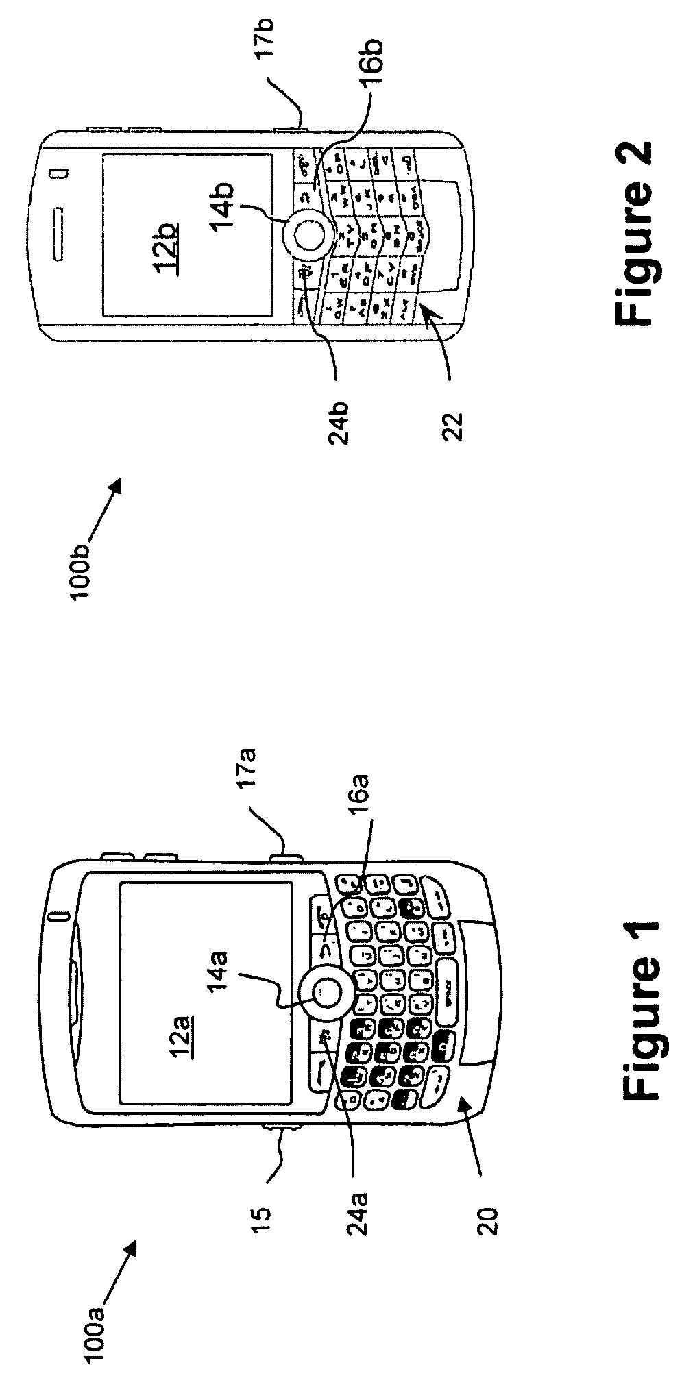
[0031]It will be appreciated that for simplicity and clarity of illustration, where considered appropriate, reference numerals may be repeated among the figures to indicate corresponding or analogous elements. In addition, numerous specific details are set forth in order to provide a thorough understanding of the embodiments described herein. However, it will be understood by those of ordinary skill in the art that the embodiments described herein may be practiced without these specific details. In other instances, well-known methods, procedures and components have not been described in detail so as not to obscure the embodiments described herein. Also, the description is not to be considered as limiting the scope of the embodiments described herein.

[0032]In the field of electronic devices, push keys may be used to activate functions within the device. The operation of input devices, for example push keys may depend on the type of electronic device and the applications of the device...


PUM


Abstract

A switch assembly is provided to actuate a pair of switches using a single key cap, e.g. for a camera that utilizes a first switch to activate an image focusing function and a second switch to activate a camera shutter. The switch assembly comprises an inner switch and an outer switch, wherein the outer switch partially or completely surrounds the perimeter of the inner switch. The outer switch comprises an upper conductive surface and a lower conductive surface that, when in contact, electrically couples two terminals for closing a circuit. The inner switch comprises an actuator and a dome switch. When the key cap receives a first downward force, only the outer switch becomes activated and a first electric circuit is completed. When the key cap receives a second downward force that is greater than the first force, the dome switch collapses and a second electric circuit is completed.

Description

[0001]This application claims priority from U.S. Application No. 61 / 103,789, filed on Oct. 8, 2008 the contents of which are incorporated herein by reference.TECHNICAL FIELD[0002]The following relates generally to switches, and more particularly to two-stage electrical switches.DESCRIPTION OF THE RELATED ART[0003]In electronic devices, such as digital camera devices, there may be different functions corresponding to various keys with which the user interacts. For example, in a camera, one key may allow the user to control the on / off functionality, while an ancillary key controls the camera shutter. As the number of functions of electronic devices increases, it is expected that the number of user control keys would also increase, which can lead to over crowding of keys and increased user interface complexity.[0004]There are various switch devices that combine two separate switches into a single key. For example, a camera may provide the focusing function and the camera shutter functi...

Claims


Application Information

Patent Timeline
Patent Type & Authority Patents(United States)
IPC IPC(8): H01H9/00
CPCH01H13/503H01H13/64H01H2203/044H01H2215/004H01H2225/018
Inventor RAJAGOPAL, VIJAISULEM, FIRMANSYAHKYOWSKI, TIMOTHYINFANTI, JAMES
Owner MALIKIE INNOVATIONS LTD
Learn More