
Process for the production of phenylalkanes that uses at least two alkylation reactors in parallel

a technology of alkylation reactor and phenylalkane, which is applied in the direction of organic chemistry, transportation and packaging, hydrocarbon preparation catalysts, etc., can solve the problems of difficult implementation, waste removal, and severe safety problems, and achieve the effect of limiting the deactivation and considerably prolonging the cycle duration of the alkylation reaction

Inactive Publication Date: 2011-11-15
INST FR DU PETROLE
View PDF7 Cites 0 Cited by
  • Summary
  • Abstract
  • Description
  • Claims
  • Application Information

AI Technical Summary

Benefits of technology

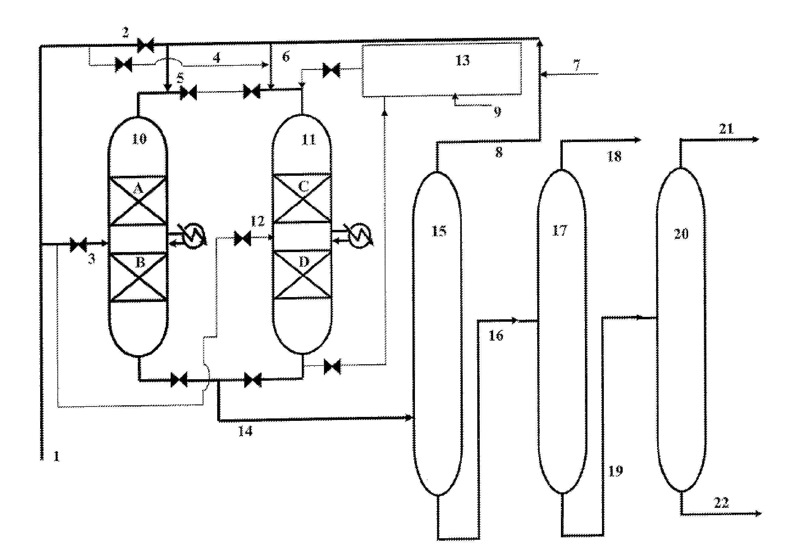
[0012]The object of this invention is a process for the production of phenylalkanes that comprises at least:
[0013]a) A reaction for alkylation of at least one aromatic compound by at least one olefin that has 9 to 16 carbon atoms per molecule, whereby said reaction is carried out in at least a first catalytic alkylation reactor within which n reaction zones that each contain at least one acidic solid catalyst are present, whereby n is greater than or equal to 2, and at the inlet of each of which at least one fraction of the total amount of olefins necessary to said reaction is introduced,
[0014]b) The separation of at least a portion of the effluent that is obtained from stage a) to recover the excess reagents, on the one hand, and the phenylalkanes, on the other hand,
[0015]c) The reactivation of each acidic solid catalyst that is present in each of n reaction zones of at least a second catalytic alkylation reactor that is placed in parallel relative to said reactor(s) used in said stage a), whereby n is greater than or equal to 2, and
[0016]d) The periodic switching of functions carried out by at least said first catalytic alkylation reactor used in stage a) and at least said second catalytic alkylation reactor that is used in stage c) such that at least said first reactor that is initially used in said stage a) is used under the conditions of said stage c) at the end of a duration that is at least equal to 5 hours and that at least said second reactor that is initially used in said stage c) is used under the conditions of said stage a). The olefins that are used as an alkylating agent in the catalytic alkylation reactor(s) operating in alkylation mode to produce phenylalkanes preferably contain 10 to 14 carbon atoms per molecule. The olefins are preferably for the most part linear. The aromatic compound that is used as a reagent in the catalytic alkylation reactor(s) operating in alkylation mode is preferably benzene.
[0017]In a preferred mode of the invention, each of the reaction zones of each of the catalytic alkylation reactors contains at least the same acidic solid catalyst, preferably a zeolitic catalyst. It may also be advantageous to use the same first acidic solid catalyst in each of the reaction zones of at least said first catalytic reactor and the same second acidic solid catalyst in each of the reaction zones of at least said second catalytic reactor, whereby said first acidic solid catalyst is different from said second acidic solid catalyst.

Problems solved by technology

The main drawback of this process is linked to environmental constraints and poses severe safety problems, on the one hand, and waste removal problems, on the other hand.
In addition, the separation of the catalyst from products of the reaction is necessary and difficult to implement.
However, the primary drawback of the acidic solid catalysts is their rapid deactivation during the alkylation reaction by adsorption on the surface and on the active sites of said catalysts of hydrocarbon-containing radicals.
However, these patents teach the use of reactivation elements that increase the use of the processes or mention cycle durations that are not very compatible with an industrial operation.

Method used


Image

  • Process for the production of phenylalkanes that uses at least two alkylation reactors in parallel
  • Process for the production of phenylalkanes that uses at least two alkylation reactors in parallel

Examples


example 2

Preparation of Catalyst B Containing a Mordenite Zeolite

[0065]A mordenite zeolite in sodium form, whose chemical formula in the anhydride state is Na1AlO2(SiO2)5.1 and its sodium content is 5% by weight, is used. 100 grams of this powder is brought to reflux at 100° C. for 2 hours in a 4N ammonium nitrate solution with a V / P ratio that is equal to 4 cm3 / g. This cationic exchange operation is repeated 3 times. The content by weight of sodium of the product that is obtained is about 500 ppm (parts per million).

[0066]This product is then subjected to an acid attack using a 4.5 N nitric acid aqueous solution, and the product is brought to reflux in this aqueous solution for 2 hours with a V / P ratio that is equal to 4 cm3 / g. After this treatment, the product is washed with demineralized water.

[0067]The mordenite that is obtained has an Si / Al atomic ratio that is equal to 40 and a sodium content that is equal to 20 ppm by weight.

[0068]The thus obtained mordenite is then mixed with an alum...

example 3

Production of Phenylalkanes (According to the Invention)

[0069]Two catalytic reactors 1 and 2 in parallel, each comprising two reaction zones that contain 25 cm3 of catalyst A in the form of extrudates, prepared according to Example 1, are used.

[0070]The reactor 1 is in alkylation phase. The reactor 2 is in rejuvenation phase.

[0071]For the reactor 1, the operating conditions for the alkylation of the benzene for each reaction zone are the following:[0072]Temperature: 120° C.[0073]Pressure: 4 MPa[0074]VVG close to 2 h−1 (volume of liquid hydrocarbons per volume of catalyst and per hour)[0075]Molar ratio {benzene / dodecene−1} in each of the reaction zones≈60

[0076]A feedstock that contains 86% by weight of benzene and 14% by weight of olefins (C10-C14) is prepared. This feedstock that is introduced at the inlet of the first reaction zone contains all of the benzene that is necessary for the alkylation reaction and half the amount of olefins necessary for the alkylation reaction. The othe...

example 4

Production of Phenylalkanes (According to the Invention)

[0086]Example 3 is used again except for the nature of the acidic solid catalysts that are used. Each of the two reaction zones of each of the reactors 1 and 2 contains a catalyst that consists of a mixture of 50% by weight of catalyst A based on dealuminified Y zeolite and 50% by weight of catalyst B based on mordenite zeolite.

[0087]The operating conditions of the alkylation reaction are identical to those used in Example 3. The results that are obtained are presented in Table 2.

[0088]

TABLE 2Cycle Duration with Conversion of Olefins >95%39 hoursLinearity of the Product Obtained (% by Weight)93.5Composition of the Product (% by Weight)2-Phenylalkane50.13-Phenylalkane24.64-Phenylalkane9.25-Phenylalkane4.66-Phenylalkane3.7Didodecylbenzene (% by Weight)6.8Heavy Residue (% by Weight)1.2

[0089]The selectivity of 2-phenylalkane is equal to 50% by weight versus only 28.3% by weight in the case of Example 3. The selectivity of a particu...


PUM

PropertyMeasurementUnit
molar ratioaaaaaaaaaa

Abstract

A process for the production of phenylalkanes comprising at least two catalytic alkylation reactors placed in parallel among which are present in reaction zones that each contain at least one acidic solid catalyst, whereby n is greater than or equal to 2, is described. One of the reactors carries out the alkylation of at least one aromatic compound by at least one olefin that has 9 to 16 atoms. An olefin fraction is introduced at the inlet of each of the reaction zones of the reactor that operates in alkylation mode. While one of the reactors carries out the alkylation, the other reactor carries out the reactivation of each catalyst, partially deactivated, that it contains. The functions of each reactor are switched regularly so as to limit the deactivation of catalysts in each of the reactors.The phenylalkanes that are obtained by the process according to the invention are particularly suitable for the production of detergents.

Description

TECHNICAL FIELD[0001]This invention relates to a process for the production of phenylalkanes by alkylation of at least one aromatic compound by means of olefinic hydrocarbons that in general comprise 9 to 16 carbon atoms per molecule.[0002]The phenylalkanes that are obtained according to the process of the invention constitute precursors of choice for the formulation of detergents and in particular certain biodegradable detergents, for example after sulfonation.PRIOR ART[0003]Currently, the bases for biodegradable detergents rely greatly on alkylbenzenes or phenylalkanes. The production of this type of compound is growing steadily. One of the main properties desired for these compounds, after a sulfonation stage, is, in addition to their detergent power, their biodegradability, which requires that these products be linear alkylbenzenes (LAB) or slightly branched alkylbenzenes (MAB) according to the definition of U.S. Pat. No. 6,187,981.[0004]The alkylbenzenes that are designated abo...

Claims


Application Information

Patent Timeline
Patent Type & Authority Patents(United States)
IPC IPC(8): C07C2/66C09K23/04
CPCC07C2/66C07C15/107C07C2529/08C07C2529/18Y02P20/584
Inventor GUILLON, EMMANUELLESANCHEZ, ERIC
Owner INST FR DU PETROLE
Learn More