
Surgical instrument incorporating an electrically actuated articulation locking mechanism

a surgical instrument and locking mechanism technology, applied in the field of surgical instruments, can solve the problems of posing numerous challenges and barriers, complicated approaches to articulating surgical stapling and severing instruments,

Active Publication Date: 2011-11-15
CILAG GMBH INT
View PDF231 Cites 1175 Cited by
  • Summary
  • Abstract
  • Description
  • Claims
  • Application Information

AI Technical Summary

Benefits of technology

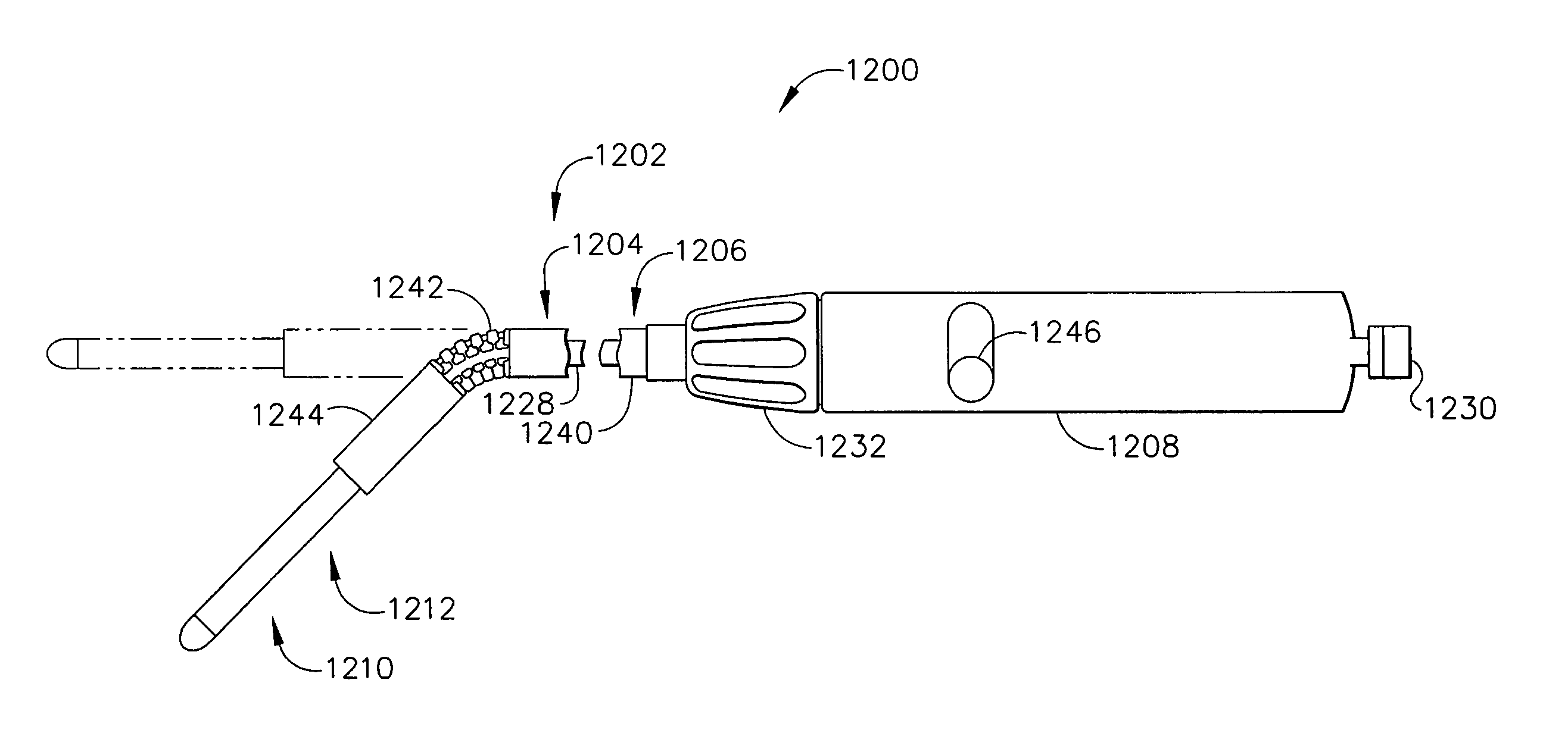
[0012]The invention overcomes the above-noted and other deficiencies of the prior art by providing a surgical instrument having an articulating shaft attached between a handle and an end effector. An electroactive polymer (EAP) actuator disengages an articulation lock during articulation and then reengages. Thereby, even a relatively weak articulation actuation mechanism may be employed with the articulation joint being locked thereafter, eliminating the need for the articulation actuation mechanism to be strong enough after actuation to prevent being backdriven. Thereby a shaft of advantageously small diameter may be achieved, yet have the functionality of remotely controllable actuation.

Problems solved by technology

Approaches to articulating a surgical stapling and severing instrument tend to be complicated by integrating control of the articulation along with the control of closing the end effector to clamp tissue and fire the end effector (i.e., stapling and severing) within the small diameter constraints of an endoscopic instrument.
While these mechanically communicated articulation motions have successfully enabled an endoscopic surgical stapling and severing instrument to articulate, development trends pose numerous challenges and barriers to entry into the market.
However, these generally known articulation mechanisms have to remain robust enough to withstand being back driven by loads on the end effector.

Method used


Image

  • Surgical instrument incorporating an electrically actuated articulation locking mechanism
  • Surgical instrument incorporating an electrically actuated articulation locking mechanism
  • Surgical instrument incorporating an electrically actuated articulation locking mechanism

Examples


Embodiment Construction

Overview Of Articulating Shaft.

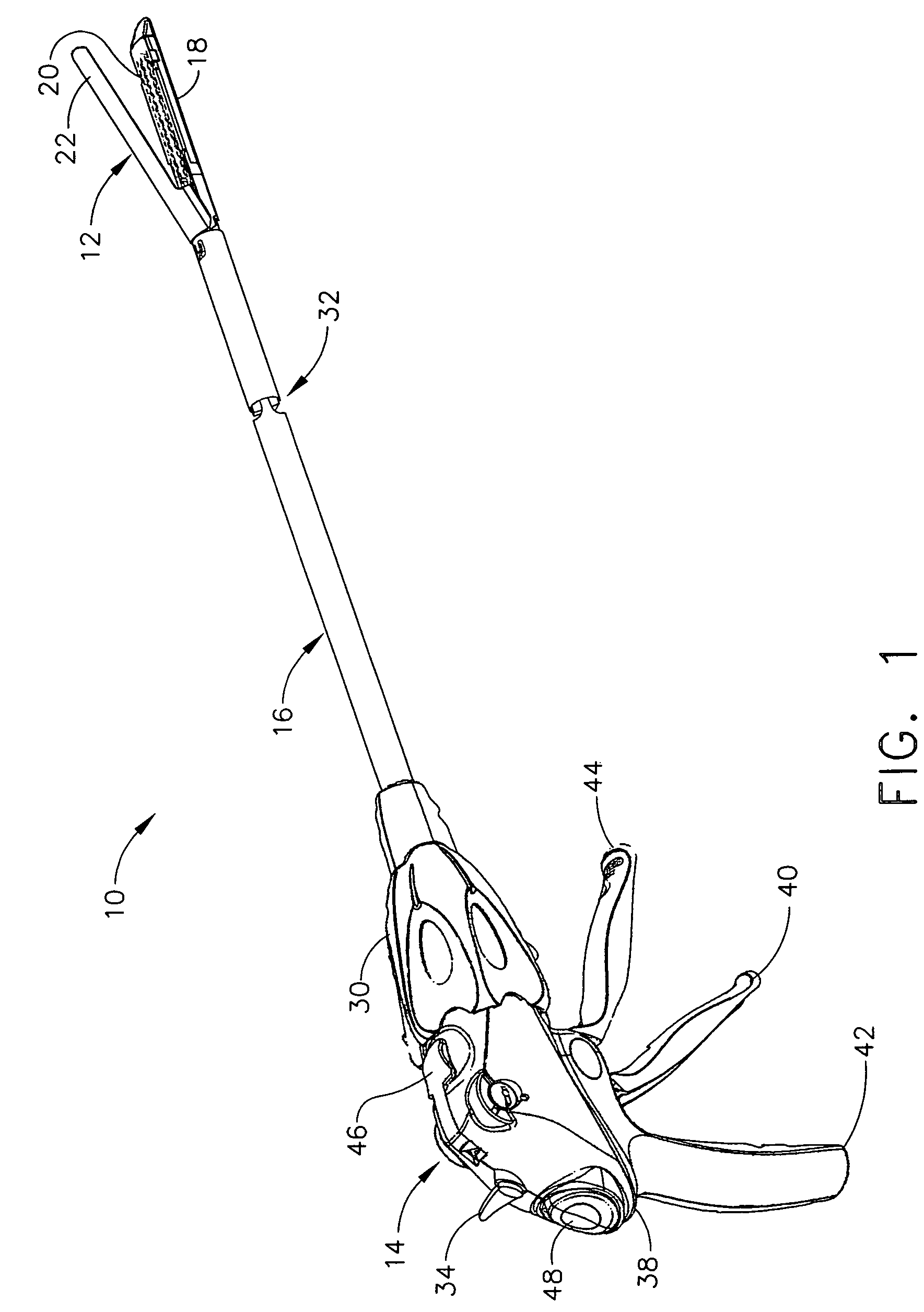
[0062]In FIG. 1, a surgical instrument, depicted as a surgical severing and stapling instrument 10, has at its distal end an end effector of a staple applying assembly 12, spaced apart from a handle 14 by an elongate shaft 16. The staple applying assembly 12 includes a staple channel 18 for receiving a replaceable staple cartridge 20. Pivotally attached to the staple channel 18 is an anvil 22 that clamps tissue against the staple cartridge 20 for stapling and severing. When the staple applying assembly 12 is closed, its cross sectional area, as well as the elongate shaft 16 are suitable for insertion through a small surgical opening, such as through a cannula of a trocar (not shown).

[0063]Correct placement and orientation of the staple applying assembly 12 is facilitated by controls on the handle 14. In particular, a rotation knob 30 causes rotation of the shaft 16 about its longitudinal axis, and hence rotation of the staple applying assembly 12. Addi...


PUM


Abstract

A surgical instrument particularly suited to endoscopic use articulates an end effector by including an articulation mechanism in an elongate shaft that incorporates an electrically actuated polymer (EAP) articulation locking mechanism actuator. Thereby, additional options for articulation become feasible, especially those that are actively powered and would otherwise dissipate heat and power if required to maintain position. Alternatively, a mechanically actuated articulation mechanism may be designed with reduced strength, and thus size, since the EAP articulation lock mechanism assists in preventing back driving after articulation. Versions of a. EAP articulation locking mechanism lock a pivoting articulation joint and others lock a flexible neck articulation joint.

Description

CROSS REFERENCE TO RELATED APPLICATIONS[0001]This application claims the benefit of U.S. provisional application Ser. No. 60 / 591,694, entitled “SURGICAL INSTRUMENT INCORPORATING AN ELECTRICALLY ACTUATED ARTICULATION MECHANISM” to Shelton IV, filed 28 Jul. 2004.FIELD OF THE INVENTION[0002]The present invention relates in general to surgical instruments that are suitable for endoscopically inserting an end effector (e.g., endocutter, grasper, cutter, staplers, clip applier, access device, drug / gene therapy delivery device, and an energy device using ultrasound, RF, laser, etc.) to a surgical site, and more particularly to such surgical instruments with an articulating shaft.BACKGROUND OF THE INVENTION[0003]Endoscopic surgical instruments are often preferred over traditional open surgical devices since a smaller incision tends to reduce the post-operative recovery time and complications. Consequently, significant development has gone into a range of endoscopic surgical instruments that...

Claims


Application Information

Patent Timeline
Patent Type & Authority Patents(United States)
IPC IPC(8): A61B17/50
CPCA61B17/07207A61B17/29A61B17/00234A61B2017/2927A61B2017/2904A61B2017/00871A61B2017/00398A61B17/04A61B17/00A61B17/122
Inventor SHELTON, IV, FREDERICK E.
Owner CILAG GMBH INT
Learn More