Device for marking a wind power plant

a technology for wind power plants and markings, applied in the direction of propellers, propulsive elements, water-acting propulsive elements, etc., can solve the problems of disproportionately high complication and expenditure, and the considerable increase in the production cost of rotor blades, so as to avoid the disadvantages of blades, easy to modify, and simple daytime identification

Active Publication Date: 2011-11-15
WOBBEN ALOYS
View PDF19 Cites 1 Cited by
  • Summary
  • Abstract
  • Description
  • Claims
  • Application Information

AI Technical Summary

Benefits of technology

[0007]The object of the present invention is to provide a simple daytime identification which can be easily modified and which avoids the disadvantages of the blades identified by color marking.
[0013]By virtue of the edge of the opening of the sheath being of a particularly tear-resistant nature and by virtue of at least one particularly tear-resistant fixing means being fitted thereto, even in the event of failure of other fixing means, it is possible to prevent unwanted release of the sheath and thus to prevent it from uncontrolledly dropping off or blowing away with the loss of the sheath which that almost inevitably entails.
[0014]In a particularly preferred development of the invention the inside of the sheath is cushioned with a material which is softer than the rotor blade surface. That can reliably prevent the rotor blade surface from being damaged by the sheath. Furthermore the sheath can then already be pulled on to the rotor blade on the ground and can then already serve as a protective sheath when handling the rotor blade. In that case the sheath can be particularly reinforcedly cushioned in particular at the locations at which the rotor blade is carried for example by a crane.
[0015]For that purpose the sheath can particularly preferably substantially extend over the entire rotor blade length. By virtue thereof, fitting or removal of additional cushions prior to or after handling of the rotor blade can be avoided and thus the procedure can be simplified. That therefore affords adequate cushioning to protect the rotor blade from damage, for example by a crane harness.

Problems solved by technology

While the nighttime identification can be ensured with energy storage devices which are charged up during the day even during the building phase when the installation cannot yet be supplied with power from the mains network, that is possible for a daytime identification with white light, only with disproportionately high complication and expenditure.
In addition however fitting blades identified in red-white-red would admittedly make a daytime identification with white light obsolete, but that signifies a considerable increase in expense in production of the rotor blades.

Method used


Image

  • Device for marking a wind power plant
  • Device for marking a wind power plant
  • Device for marking a wind power plant

Examples


first embodiment

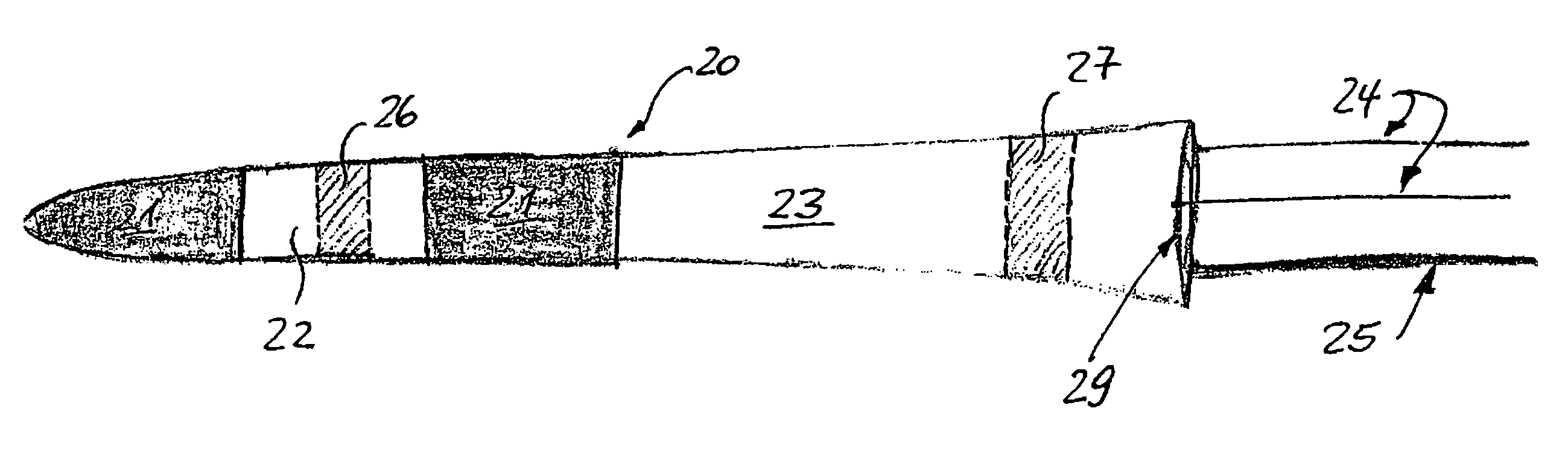
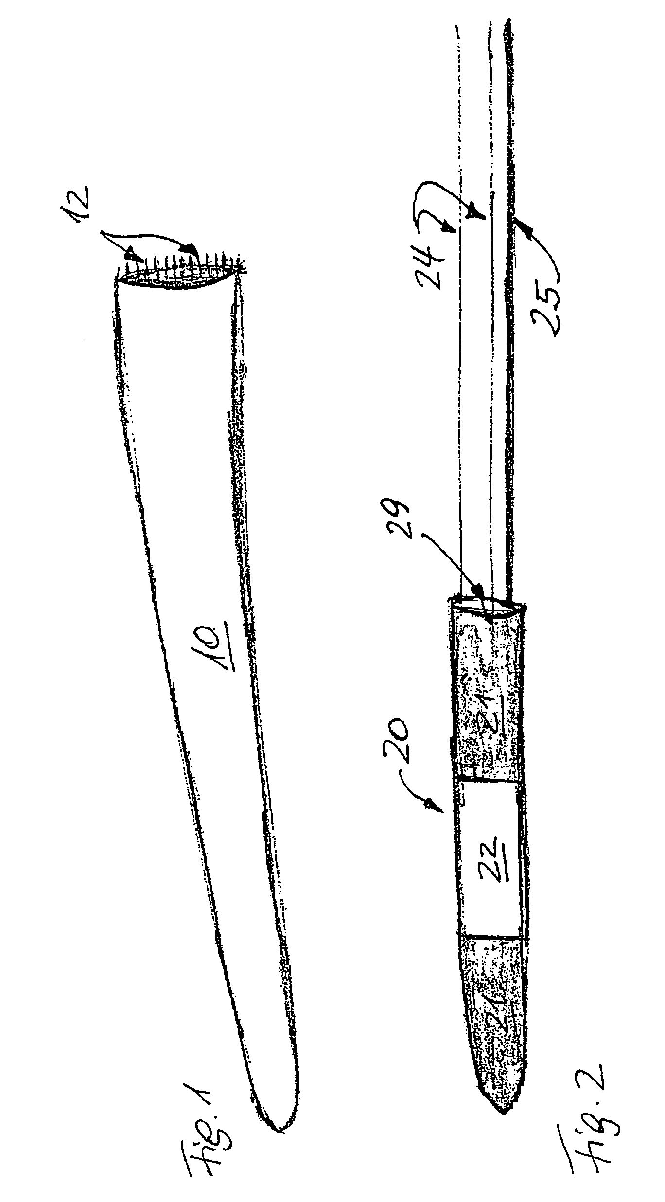
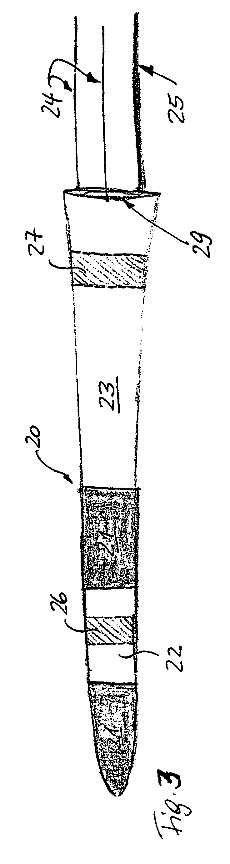
[0025]FIG. 3 shows an alternative embodiment of the sheath 20 according to the invention. In this alternative embodiment, once again beginning at the rotor blade tip, there are a red portion 21, a white portion 22 and once again a red portion 21, which comply with the requirements for daytime identification, just as is the case with the sheath 20 shown in FIG. 2.

second embodiment

[0026]In this second embodiment however, there is in adjoining relationship a further region 23 whose coloration is however not necessarily prescribed. That region 23 can be for example white but it can also be transparent. It can even be provided for example with a logo or another reference to the manufacturer of the wind power installation and / or the rotor blade.

[0027]It will be appreciated that the second embodiment of the sheath 20 is also open at one end and once again cables 24, 25 are fitted as securing means to the edge 29 of that open end, the cables permitting the sheath 20 to be fixed for example in the region of the rotor blade root to the hub or to the hub fairing.

[0028]It will be appreciated that the edge 29 can also once again be particularly reinforced and a particularly strong cable 25 can be provided in order reliably to prevent the sheath 20 from coming loose from the rotor blade even in the event of failure of the other cables 24.

[0029]This Figure shows a cushion...


PUM


Abstract

The present invention concerns a wind power installation and in particular the identification of a wind power installation as an aviation obstruction. The object of the present invention is to provide a simple daytime identification which can be easily modified and which avoids the disadvantages of the blades identified by color marking. Apparatus for temporary signal identification of a wind power installation wherein the apparatus comprises a sheath which is of a predetermined colored configuration and also has releasable fixing means for releasably fixing the sheath to a rotor blade of the wind power installation, wherein during fixing the sheath at least partially encloses the rotor blade.

Description

BACKGROUND OF THE INVENTION[0001]1. Field of the Invention[0002]The present invention concerns a wind power installation and in particular the identification of a wind power installation as an aviation obstruction.[0003]2. Description of the Related Art[0004]Such an identification has been previously described and is basically distinguished on the basis of daytime identification and nighttime identification. While nighttime identification is always lighting with red light, the daytime identification can be effected selectively with white light or alternatively with colored (red / white) markings on the rotor blade. Those color markings (signal markings) are usually red-white-red from the rotor blade tip and each of those portions must be of a length of about 6 meters or more, in accordance with the current construction requirements.[0005]While the nighttime identification can be ensured with energy storage devices which are charged up during the day even during the building phase when...

Claims


Application Information

Patent Timeline
Patent Type & Authority Patents(United States)
IPC IPC(8): F03D11/00
CPCF03D1/0608F03D11/00F03D11/0041Y02E10/722Y02E10/721F03D80/00F03D80/10Y02E10/72F03D1/0658F05B2240/20
Inventor WOBBEN, ALOYS
Owner WOBBEN ALOYS
Why Eureka
Try Eureka