Eureka AIR delivers breakthrough ideas for toughest innovation challenges, trusted by R&D personnel around the world.

Apparatus for surface mixing of gasses and liquids

a surface mixing and liquid technology, applied in the direction of combustion air/fuel air treatment, machines/engines, chemical/physical processes, etc., can solve the problems of reducing the efficiency of fouled materials, and sulfide can produce objectionable odors. the effect of promoting aeration

Inactive Publication Date: 2011-11-15
HILLS BLAIR H
View PDF61 Cites 1 Cited by
  • Summary
  • Abstract
  • Description
  • Claims
  • Application Information

AI Technical Summary

Benefits of technology

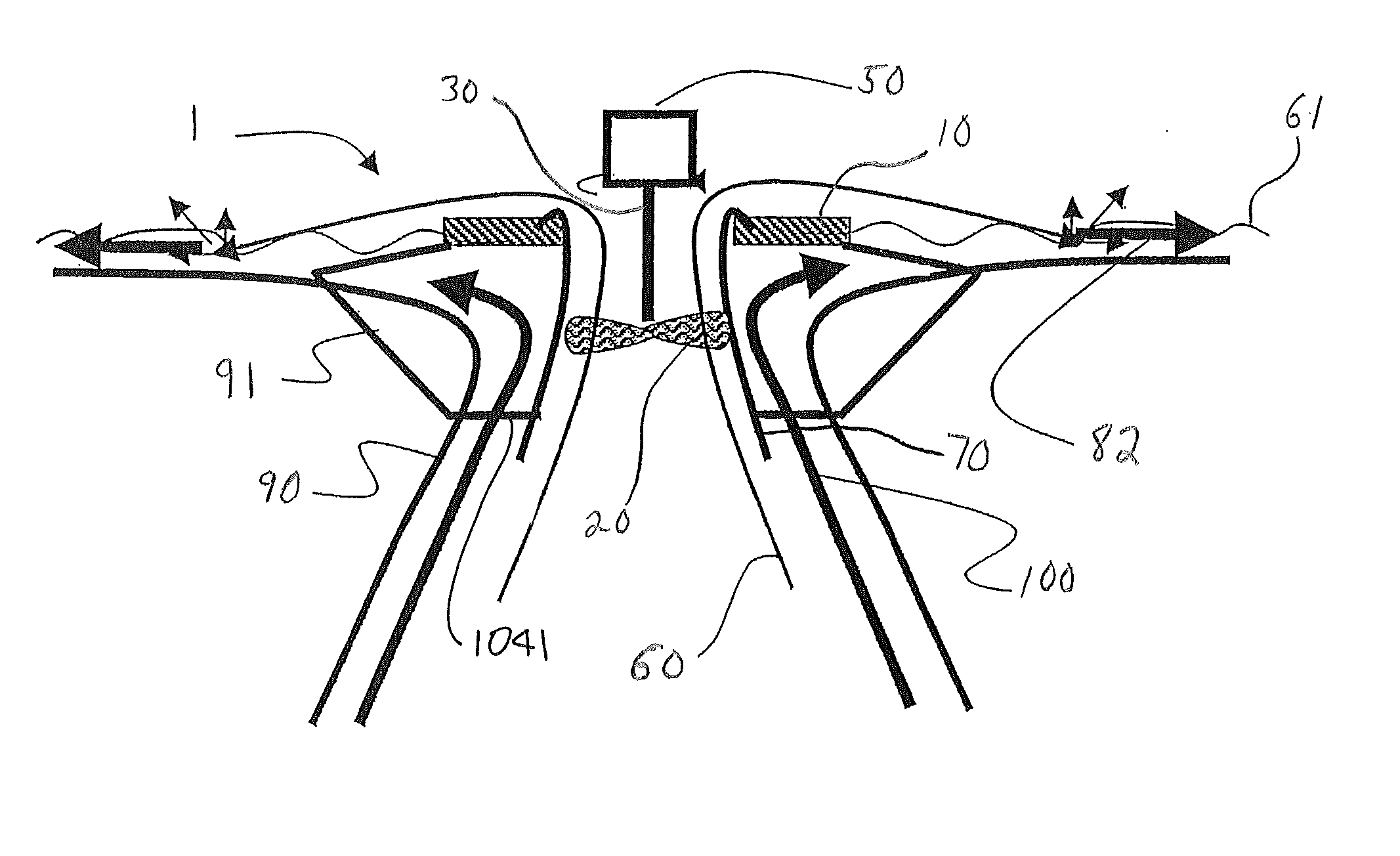
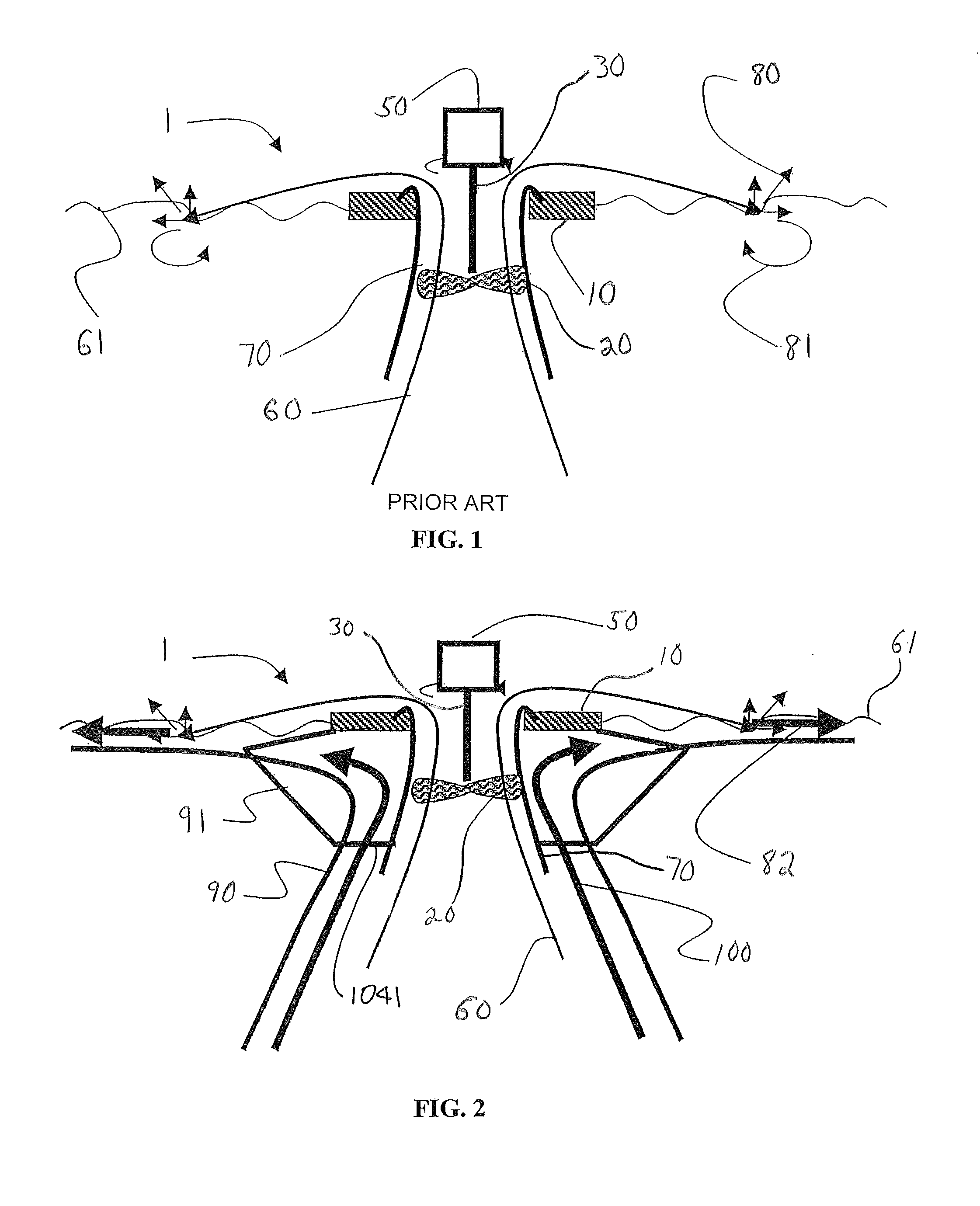
[0017]The present invention provides a surface aerator for mixing gas and liquid. The surface aerator has an upwardly pumping impeller located within a draft tube. A flow diverter redirects pumped liquid from the impeller traveling in an upward direction to a radially outward direction where it impacts and aerates the remaining liquid in a vessel. A baffle extends radially at a shallow depth to a point beyond the impact area of the liquid to provide separation of the impact area from the remainder of the liquid in a tank and promote aeration.

Problems solved by technology

Even small quantities of hydrogen sulfide can produce objectionable odors thereby necessitating that oxygen be mixed into the liquid.
However, these porous materials are easily fouled and can become blocked when placed in dirty liquids, liquids having a high particulate concentration or high soluble mineral concentration.
Fouled materials reduce efficiency, increase operational energy cost, and increase bubble size.
Porous materials can also stretch over time, thereby increasing hole size and bubble formation diameter, or harden, thereby causing increased pressure.
Larger bubbles, caused by larger hole size, increased pressure or fouling, reduce the available gas-liquid surface area, which reduces the overall Standard Aeration Efficiency (SAE).
Periodic cleaning and maintenance often involve expensive and hazardous HCl injections into the diffuser system and / or the emptying of the aeration vessel followed by physical cleaning.
Plastic membranes must be periodically changed, which increases labor, materials and processing costs associated with an aeration system shut-down during installation.
Their efficiency, even when clean, is frequently reduced by the intensity of the liquid mixing.
Other traditional mechanical diffused aeration systems do not use a compressor, however, these systems require a vortex or a venturi system to create gas pockets at some depth below the surface of the liquid.
However, surface aerators achieve low gas utilization and require large volumes of gas to be mixed with liquid, causing a high rate of off-gassing, which strips volatile organics from the liquid into the gas.

Method used


Image

  • Apparatus for surface mixing of gasses and liquids
  • Apparatus for surface mixing of gasses and liquids
  • Apparatus for surface mixing of gasses and liquids

Examples


Embodiment Construction

[0024]Referring now to FIG. 1, a prior art mixer 1 is shown. The mixer 1 is a high-speed surface aerator mounted on a float 10. The mixer 1 may also be a low-speed surface aerator. FIG. 1 illustrates a prior art version of a surface aerator type mixer 1. The mixer 1 includes an impeller 20 mounted on a drive 30. The drive 30 may include a motor, power converter, drive shaft, gearbox and driven shaft. A flow diverter 50 mounted above the impeller 20 redirects fluid flowing upward to a horizontal direction. The impeller 20 is located within a draft tube 70. The liquid flow path 60 shows that fluid is drawn from below the draft tube and accelerated to about 15-20 feet per second and is diverted from a vertical direction to a horizontal direction, ultimately impacting the surface of the water. At the point of impact, liquid splashes 80 project from the liquid surface 61. The high-speed liquid causes gas to liquid mass transfer and generally the liquid is pushed or jetted radially outwar...


PUM

PropertyMeasurementUnit
depthaaaaaaaaaa
depthaaaaaaaaaa
elevationaaaaaaaaaa

Abstract

A surface aerator for mixing gas and liquid is disclosed. The surface aerator has an upwardly pumping impeller located within a draft tube. A flow diverter redirects pumped liquid from the impeller traveling in an upward direction to a radially outward direction where it impacts and aerates the remaining liquid in a vessel. A baffle extends radially at a shallow depth to a point beyond the impact area of the liquid to provide separation of the impact area from the rest of the liquid and promote aeration.

Description

CROSS REFERENCE TO RELATED APPLICATION[0001]This invention claims the benefit of U.S. Provisional Application Ser. No. 60 / 763,257 filed Jan. 30, 2006. This application is related to U.S. application Ser. No. 11 / 668,816, filed Jan. 30, 2007 to Blair Howard Hills. Both of which are herein incorporated by reference.FIELD OF THE INVENTION[0002]The present invention relates to gas and liquid mixers for use in various applications such as wastewater systems, chemical reactors, mass transfer systems and the like.BACKGROUND INFORMATION[0003]Gas-liquid mixing systems are conventionally used for many purposes, such as the mass transfer of gases into and / or out of liquids. Oxidation and reduction reactions often require that a gas, such as oxygen, chlorine or hydrogen, be mixed with liquids in the presence of solids. Unwanted gases dissolved in liquids can be stripped from the liquid by mixing a desired gas into the liquid. Direct contact heating of a liquid requires that a hot gas be mixed in...

Claims


Application Information

Patent Timeline
Patent Type & Authority Patents(United States)
IPC IPC(8): B01F3/04
CPCB01F3/04539B01F3/04588B01F3/04609B01F5/0212B01F7/00341B01F7/00358B01F7/00733B01F7/00916B01F7/00975B01F7/021B01F7/1635B01F7/166B01F13/0049B01F15/00993C02F3/16B01F2003/04546B01F2003/0456B01F2003/04567B01F2015/00116B01F2015/00623B01F2215/0427B01F2215/0431Y02W10/10B01F23/2331B01F23/23311B01F23/23313B01F23/23314B01F23/2332B01F23/23341B01F25/211B01F27/1132B01F27/113B01F27/25B01F27/55B01F27/2322B01F27/61B01F27/8111B01F27/84B01F33/503B01F2035/353B01F35/33B01F35/189
Inventor HILLS, BLAIR H.
Owner HILLS BLAIR H
Why Eureka
Eureka Blog
Learn More