
Wide crop pick-up having primary and secondary stripper plates for converging augers respectively mounted to movable crop guide plate portion and to fixed walls behind the augers

a crop pickup and stripper plate technology, applied in baling, agriculture tools and machines, agriculture, etc., can solve problems such as losing their effectiveness in preventing

Active Publication Date: 2011-11-15
DEERE & CO
View PDF13 Cites 32 Cited by
  • Summary
  • Abstract
  • Description
  • Claims
  • Application Information

AI Technical Summary

Benefits of technology

[0005]According to the present invention, there is provided a novel wide crop pick-up which effectively delivers crop to an inlet of a container to which crop material is being fed by the pick-up while operating to avoid, or at least significantly reduce, plugging.
[0006]An object of the invention is to provide a wide crop pick-up with a crop guide plate assembly having a major guide plate portion extending substantially the full width of the pick-up and being mounted for controlled vertical movement relative to converging augers and a crop feed rotor, and to equip the pick-up with a stripper plate arrangement that is effective to strip crop from the augers even when the major guide plate portion is moved downwardly from a normal working position so as to avoid or reduce plugging.

Problems solved by technology

A problem associated with the device of the EP publication is that with such devices it is known to provide right and left stripper plates on the front of the crop guide plate arrangement at respective locations in front of the right and left converging augers.
When loads acting on the guide plate arrangement cause it to move downwardly from its normal working position in order to avoid a plugging situation, these stripper plates move with the guide plate arrangement and lose their effectiveness in preventing crop material from wrapping around the augers.

Method used


Image

  • Wide crop pick-up having primary and secondary stripper plates for converging augers respectively mounted to movable crop guide plate portion and to fixed walls behind the augers
  • Wide crop pick-up having primary and secondary stripper plates for converging augers respectively mounted to movable crop guide plate portion and to fixed walls behind the augers
  • Wide crop pick-up having primary and secondary stripper plates for converging augers respectively mounted to movable crop guide plate portion and to fixed walls behind the augers

Examples


Embodiment Construction

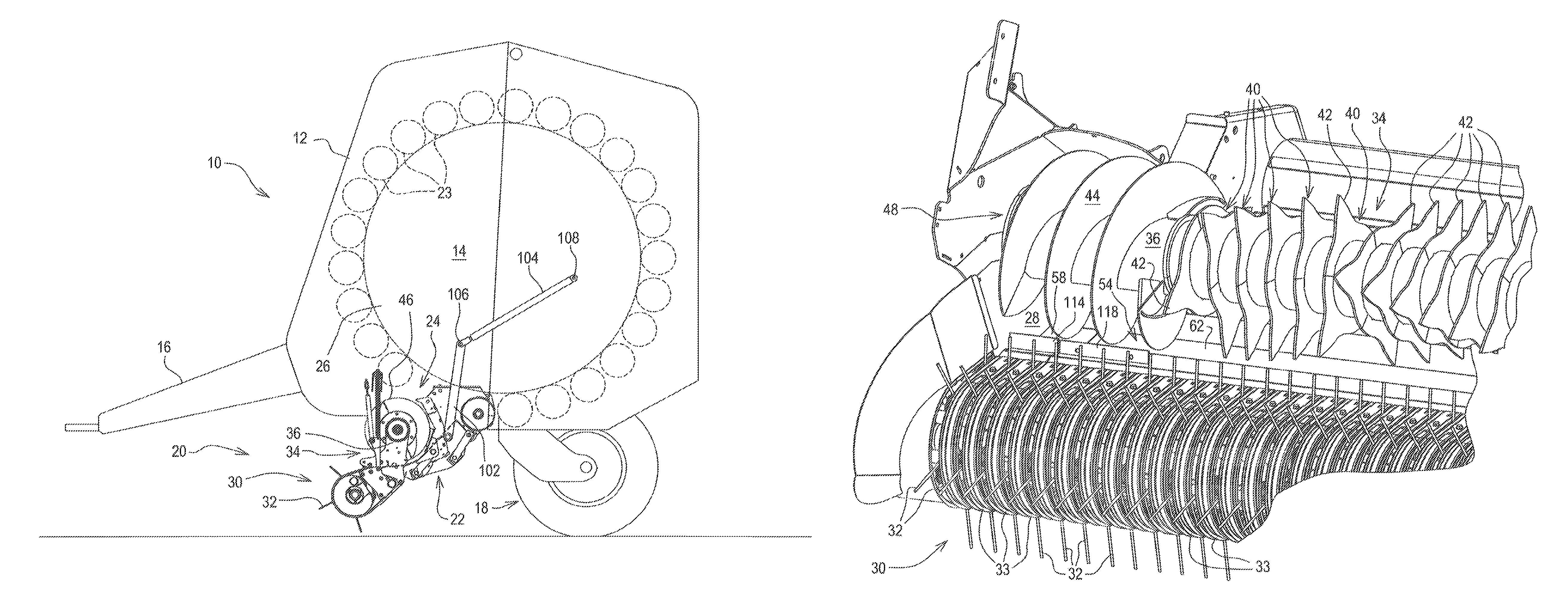
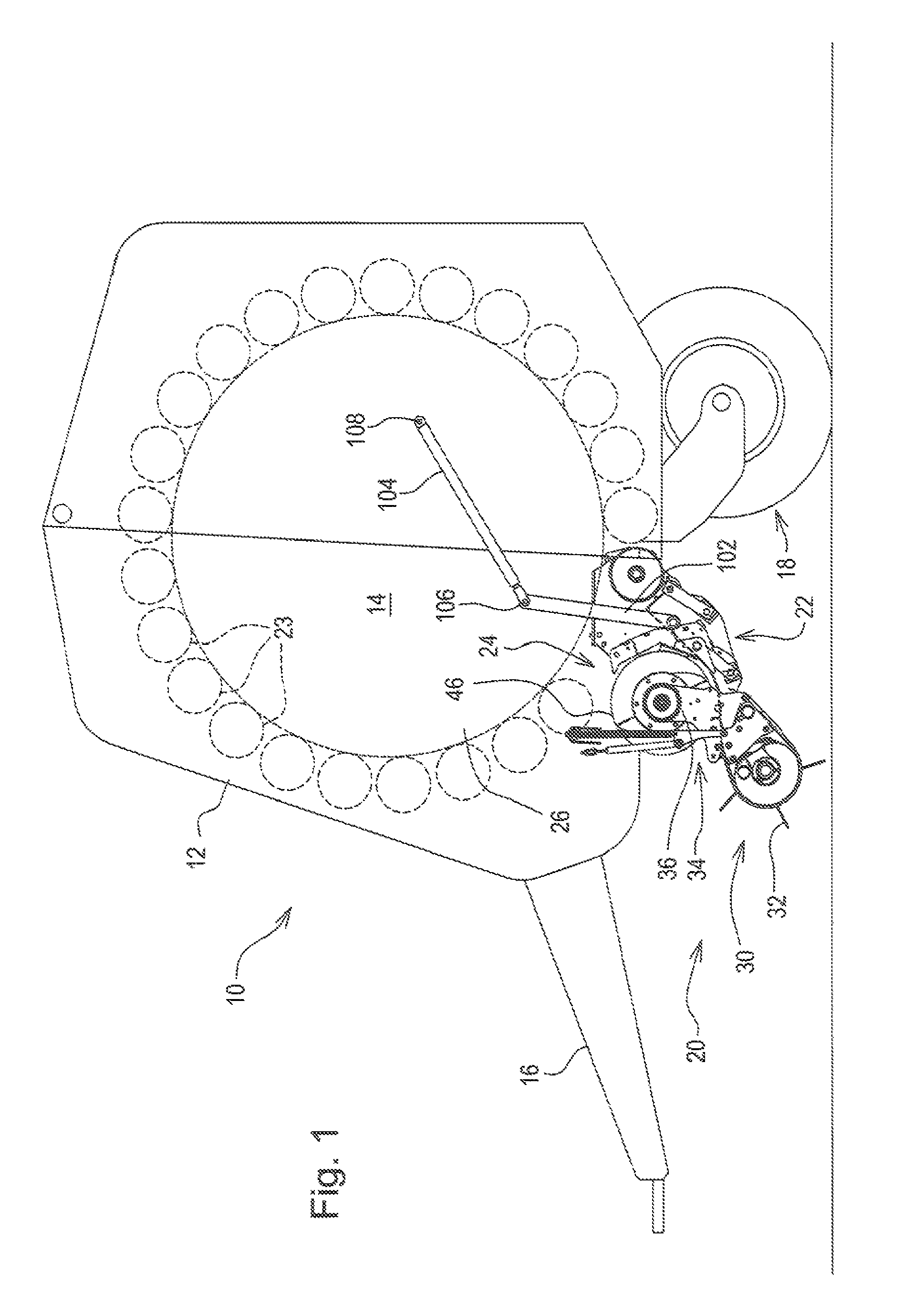
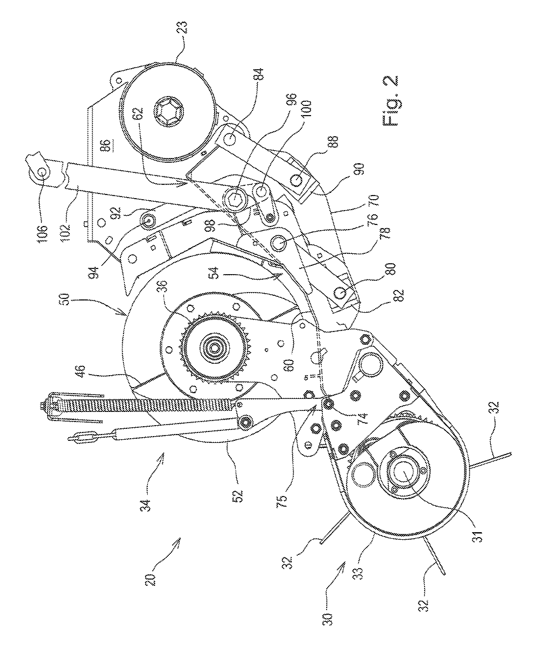
[0015]Referring now to FIG. 1, there is shown a baler 10 including a baler housing 12 defining opposite sides of a baling chamber 14 and to which is attached a drawbar 16, a pair of ground wheels 18 (only one shown), and a crop pick-up arrangement 20 including a crop conveyor arrangement 22 constructed in accordance with the present invention.

[0016]In this embodiment, the baler 10 is configured as a large round baler, with the baling chamber 14 being a fixed size defined by a plurality of rollers 23 extending transversely between opposite side walls of the housing 12 and arranged in a circular pattern leaving a gap at a lower front location thereof so as to define a crop inlet 24 for receiving crop, for example, hay, straw or silage, which is rolled by the action of the rollers 23 into a large cylindrical bale 26. Alternatively, the baler 10 could have a variable or expansible baling chamber, or the baler could be configured as a baler for producing parallelepiped bales. In the same...


PUM


Abstract

A wide pick-up for a baler includes a crop feed rotor and auger arrangement located at an elevated position rearward of a tined pick-up reel arrangement. Positioned for receiving crop delivered by the reel arrangement, and extending beneath the crop feed rotor and auger arrangement is a crop guide plate arrangement including a central movable crop guide plate portion mounted to be moved vertically between a raised feed position, wherein it is relatively close to a circular path traced by the outer peripheries of the crop feed rotor and the converging augers, and a lowered, crop unplugging position, wherein it is spaced to create a gap between the crop guide plate portion and the crop feed rotor and auger arrangement. Right and left, primary crop stripper plates are respectively mounted to right and left front end regions of the moveable crop feed plate portion, with the primary stripper plates each having an edge located close to the associated auger for preventing crop from being wrapped about the augers when the movable crop guide plate portion is in its normal raised operating position. Right and left secondary crop stripper plates are respectively mounted to right and left fixed walls extending upwardly about the augers from right and left fixed guide plate portions, these secondary stripper plates remaining in place to strip crop from the augers when the central movable crop guide plate portion is lowered.

Description

FIELD OF THE INVENTION[0001]The present invention relates to wide crop pick-ups, and more specifically relates to such pick-ups which include a crop guide plate arrangement and converging augers with stripper plates for such augers.BACKGROUND OF THE INVENTION[0002]Agricultural machines such as balers, for example, are sometimes equipped with a crop pick-up that is wider than the baling chamber or other mobile container to which the picked up crop is being conveyed. EP 08 15 720 discloses a large round baler having such a pick-up and it is equipped with a rotary, tined pick-up reel having a width greater than that of the baling chamber and operable for elevating a windrow of crop material from the ground and delivering the crop material rearward onto a crop guide plate arrangement which extends to the inlet of the baling chamber. To aid this rearward movement of the crop material, right and left converging augers are provided at opposite ends of a centrally located tined rotor. The g...

Claims


Application Information

Patent Timeline
Patent Type & Authority Patents(United States)
IPC IPC(8): A01D87/00
CPCA01F15/106
Inventor ANSTEY, HENRY D.DERSCHEID, DANIEL E.DUTERTRE, MATTHIEUOSTERMANN, PHILIPPE
Owner DEERE & CO
Learn More