
Power grid load management for plug-in vehicles

a plug-in vehicle and load management technology, applied in the direction of external condition input parameters, electric devices, navigation instruments, etc., can solve the problems of power grid architecture overloading, power grid architecture cannot be expected to handle full power demand at all electrical outlets, and the number of plug-in vehicles currently in operation is rather low

Active Publication Date: 2011-11-08
GM GLOBAL TECH OPERATIONS LLC
View PDF5 Cites 161 Cited by
  • Summary
  • Abstract
  • Description
  • Claims
  • Application Information

AI Technical Summary

Benefits of technology

This system effectively manages charging to prevent grid overload, stabilizes power distribution during peak hours, and allows for a higher integration of renewable energy sources by optimizing when and how much power is used for charging, ensuring reliable energy supply.

Problems solved by technology

The number of plug-in vehicles currently in operation is rather low.
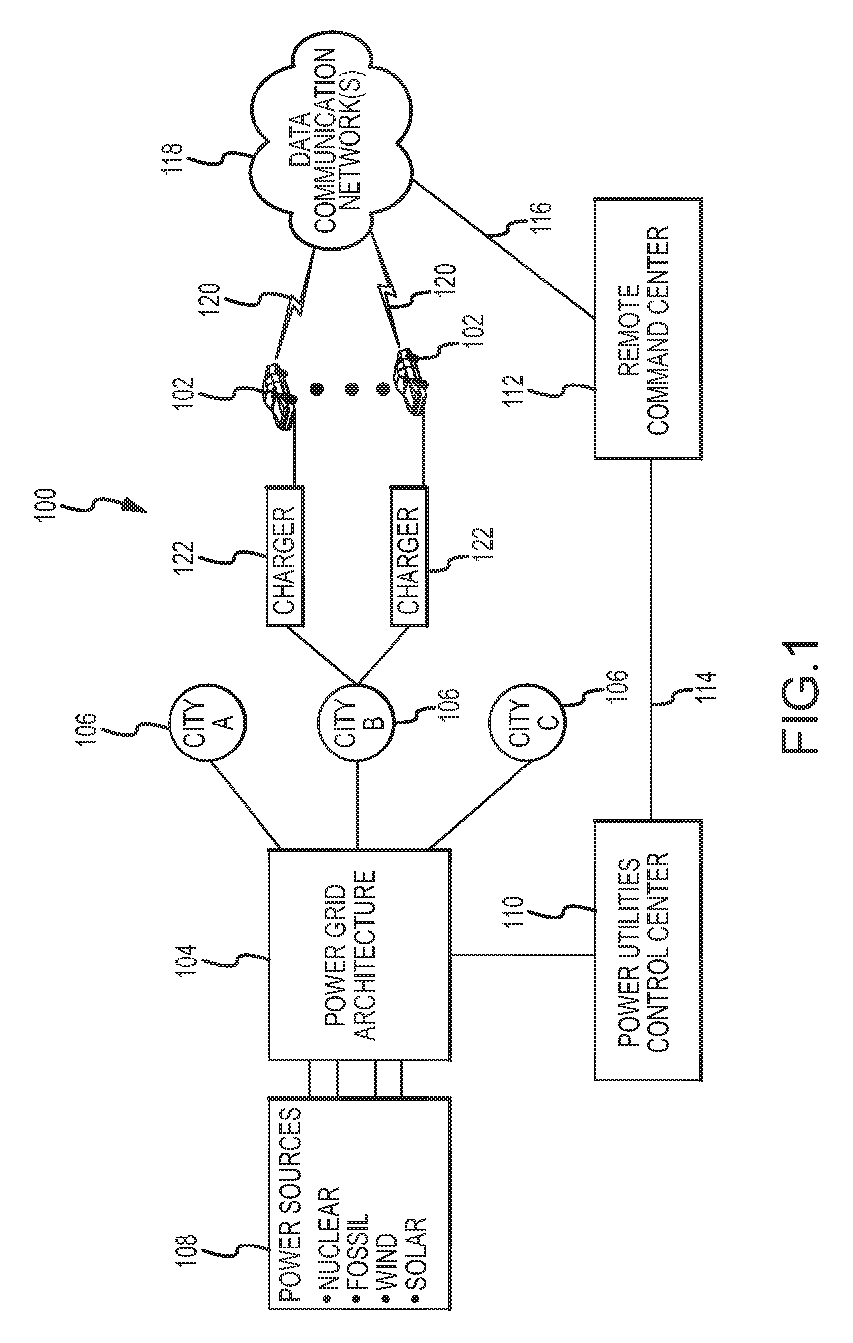
For example, overloading of a power grid architecture may occur when a large number of plug-in vehicles are concurrently plugged in for purposes of recharging.
In practice, a power grid architecture cannot be expected to handle full power demand at all electrical outlets at any given time.
Accordingly, when charging plug-in vehicles, it cannot be assumed that power from the respective power grid architecture will always be available (due to high power demands during certain hours of the day, the dependency on variable power sources such as wind generated energy and solar energy, and other practical factors).

Method used


Image

  • Power grid load management for plug-in vehicles
  • Power grid load management for plug-in vehicles
  • Power grid load management for plug-in vehicles

Examples


Embodiment Construction

[0013]The following detailed description is merely exemplary in nature and is not intended to limit the invention or the application and uses of the invention. Furthermore, there is no intention to be bound by any expressed or implied theory presented in the preceding technical field, background, brief summary or the following detailed description.

[0014]Techniques and technologies may be described herein in terms of functional and / or logical block components and various processing steps. It should be appreciated that such block components may be realized by any number of hardware, software, and / or firmware components configured to perform the specified functions. For example, an embodiment of a system or a component may employ various integrated circuit components, e.g., memory elements, digital signal processing elements, logic elements, look-up tables, or the like, which may carry out a variety of functions under the control of one or more microprocessors or other control devices....


PUM


Abstract

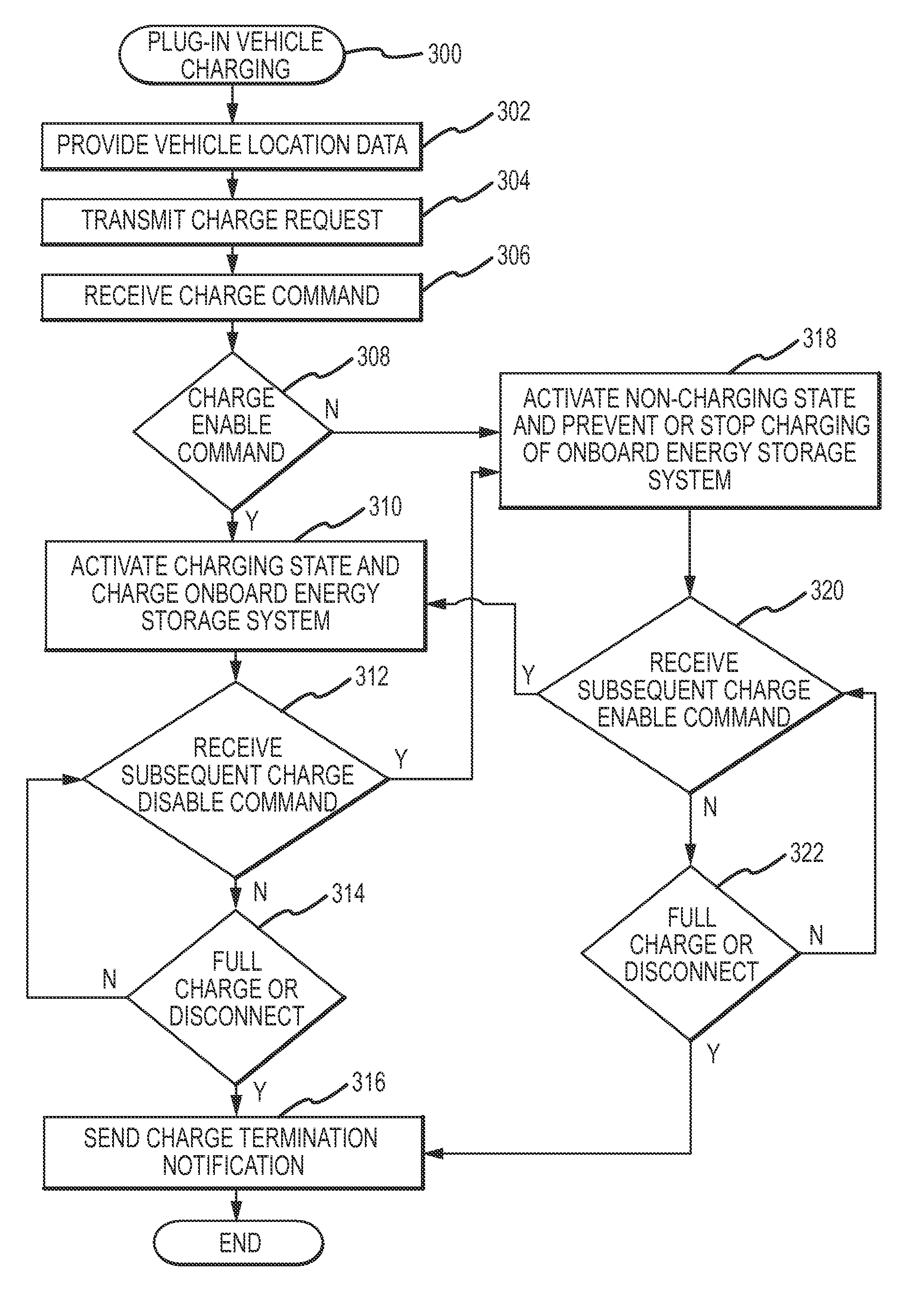
Methods and systems are provided for controlling the charging of an onboard energy storage system of a plug-in vehicle using a remote command center, such as a vehicle telematics service. An embodiment of such a method involves the transmission of a charge request for the onboard energy storage system to a remote command center associated with the plug-in vehicle. In response to the charge request, a charge command is received from the remote command center. The charging of the onboard energy storage system is regulated in accordance with the received charge command, which may be a charge enable command or a charge disable command.

Description

TECHNICAL FIELD[0001]The subject matter described herein generally relates to charging systems and methodologies for plug-in electric and hybrid electric vehicles. More particularly, the subject matter described herein relates to a system and related methods for centralized management and controlling of the charging of an onboard energy storage system of plug-in vehicles.BACKGROUND[0002]Hybrid electric and other fuel efficient vehicles are becoming increasingly popular. Plug-in hybrid electric vehicles and plug-in fully electric vehicles represent another category of vehicle that has less dependency on petroleum-based fuel. These vehicles are known as plug-in hybrid vehicles because their onboard energy storage systems (e.g., battery packs) are recharged by connecting (plugging in) the vehicle to an outlet, a charger or other voltage source, as well as from regenerative capture. In contrast to the conventional hybrid electric vehicles currently on the market, a plug-in hybrid vehicl...

Claims


Application Information

Patent Timeline
Patent Type & Authority Patents(United States)
IPC IPC(8): H02J7/04H04M11/04H04M3/42B60K1/00G01C21/30B60L50/15
CPCB60K6/48B60L11/14B60L11/1816B60L11/1838B60L11/1844B60L11/1846B60L11/1848B60L11/1887B60W10/26H01M10/48B60L11/184B60L11/1861B60L11/126Y02T10/705B60L2220/18B60L2240/62B60W20/00B60W2510/244B60W2550/402H01M10/44H02J13/0075Y02E60/721Y02T10/6217Y02T10/6221Y02T10/6269Y02T10/7077Y02T10/7291Y02T90/121Y02T90/128Y02T90/14Y02T90/16Y02T90/162Y02T90/163Y02T90/168Y02T90/169Y02T90/34Y04S10/126Y04S30/12Y04S30/14B60L2210/10B60L2210/40B60L2220/12B60L2220/14B60L2220/20B60L2240/545B60L2240/547B60L2240/549B60L2240/622B60L2240/72Y02T10/7044Y02T10/7241Y02T10/7216Y02T90/127Y02T10/7072B60L53/14B60L50/62B60L50/16B60L53/64B60L53/63B60L53/65B60L53/665B60L58/40B60W2556/50H02J2310/48H02J13/00002H02J3/14H02J2310/60H02J13/00024H02J13/00026B60L53/68B60L58/15Y02E60/00Y02T10/62Y02T10/70Y02T10/72Y02T90/12Y02T90/167Y02E60/10B60W2556/45B60W20/13B60W10/28B60W10/08Y02T90/40
Inventor WOODY, GEORGE R.WELCHKO, BRIAN A.
Owner GM GLOBAL TECH OPERATIONS LLC
Learn More