
Flexible array probe for the inspection of a contoured surface with varying cross-sectional geometry

a contoured surface and array probe technology, applied in the field of array probes, can solve the problems of eddy current sensor positioning above, difficult to inspect key aspects and difficult to achieve the effect of eddy current inspection

Active Publication Date: 2011-11-01
OLYMPUS NDT
View PDF2 Cites 12 Cited by
  • Summary
  • Abstract
  • Description
  • Claims
  • Application Information

AI Technical Summary

Benefits of technology

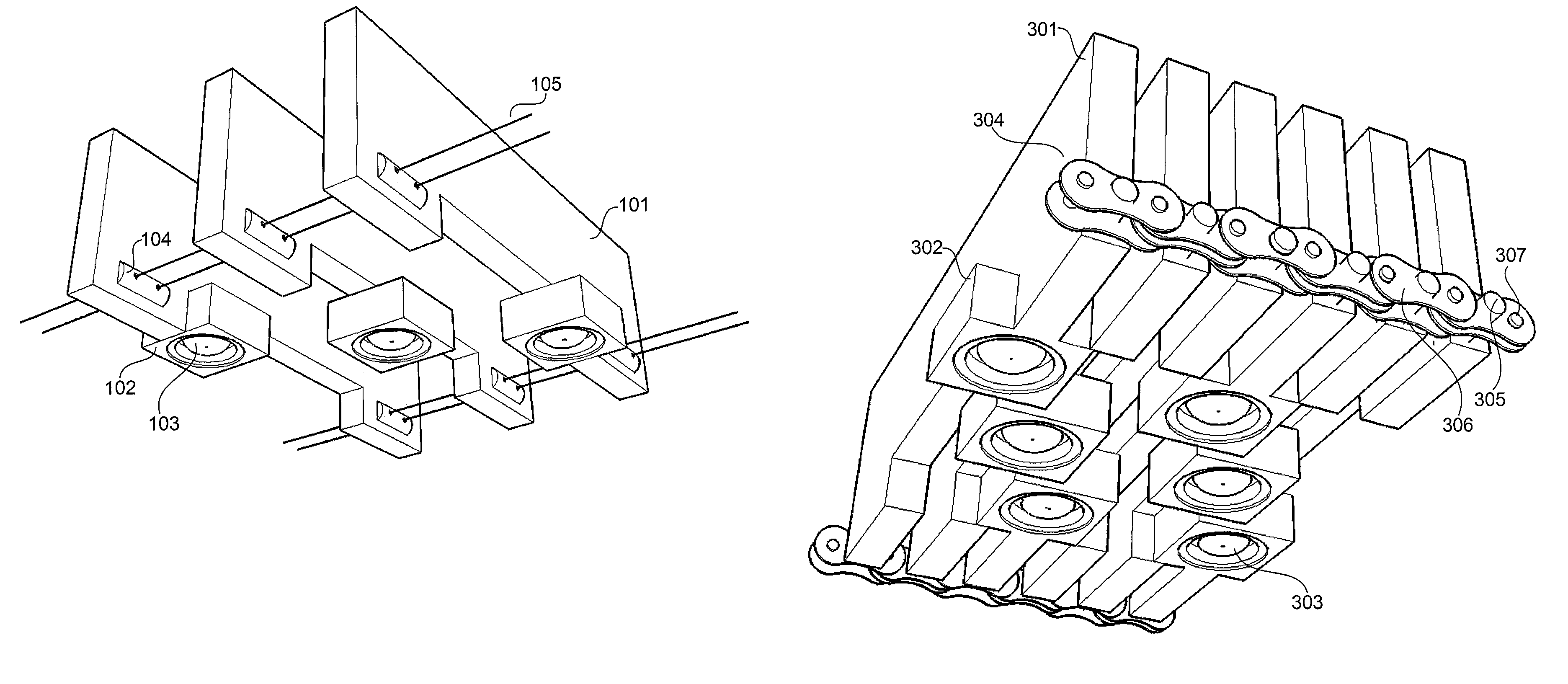
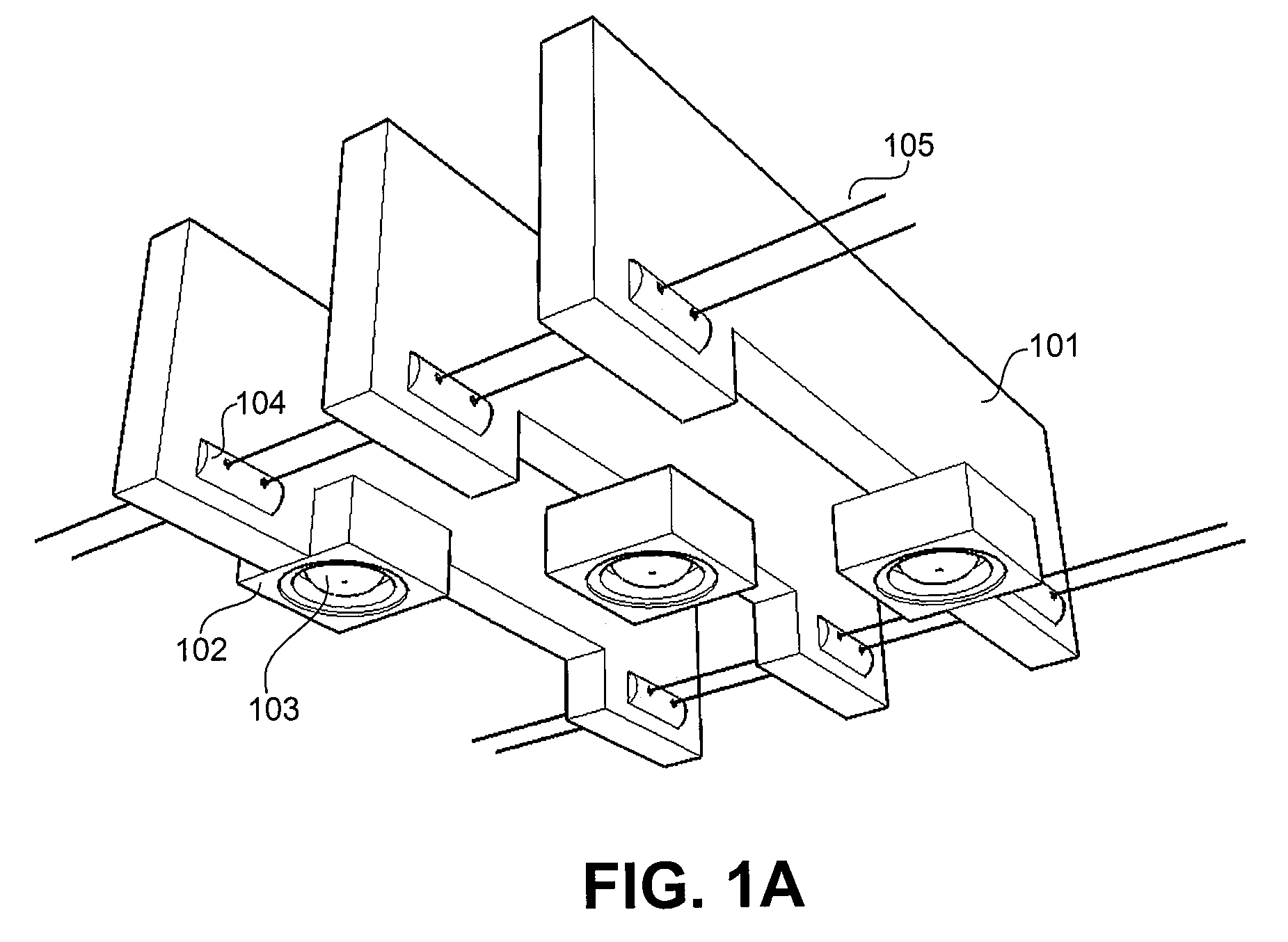
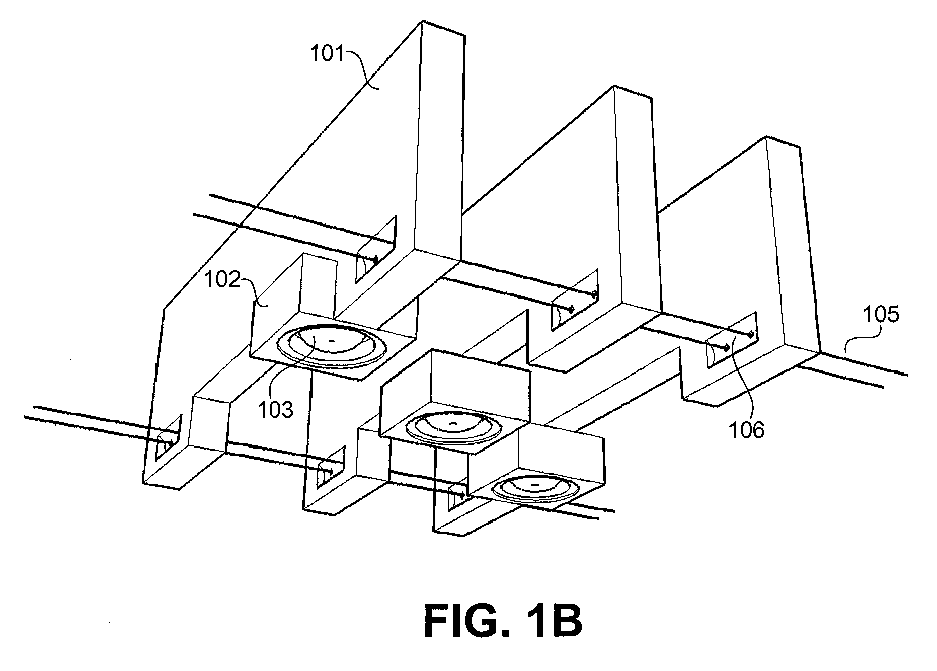
[0010]It is the object of the present disclosure to overcome the problems associated with prior art. The present disclosure does this by introducing a novel flexible array probe comprising thin array element mounting fins coupled together by pairs of pivot mechanisms located along the desired axis of rotation. The pivot mechanism pairs allow the elements of the array to rotate in exactly one dimension, while preserving a tight element arrangement and inherently aligning the elements orthogonally with the surface of the structure under test. In this way, the resulting flexible array probe will be pliant enough to respond to variations in the cross-sectional geometry of a structure under test—such as, but not limited to, variations directly relating to the manufacturing process of the structure under test—without the need for any mechanical adjustment.
[0011]Accordingly it is the object of the present disclosure to provide a robust flexible array probe built with pivot mechanisms which allow a large degree of flexibility while maintaining a tight probe element arrangement.

Problems solved by technology

Eddy current inspection of contoured surfaces has long been a challenge in non-destructive testing and inspection.
This variation on the shape of the test surface can make certain key aspects of eddy current inspection problematic.
Maintaining a constant liftoff—the height at which an eddy current sensor is positioned above a test surface—for example can become extremely difficult using a solid, inflexible eddy current array probe.
Using an eddy current array probe which holds its elements in fixed positions, this can be impossible to achieve while testing parts with varying geometry.
While Baraona's flexible array probe provides a reasonable solution to the problem of inspecting a convex surface, it holds a number of limitations.
The range of motion (rotation) of each element in the array is limited by the rigidity of the flexible bands and by the spacing of the test heads.
Both options significantly limit the usefulness of the flexible array probe.
Baraona's probe and alignment fixture also make a poor showing of maintaining orthogonal coil orientation along sharply curved surfaces.
Due to the nature of the design, each test head is allowed a degree of mobility against those directly adjacent to it, and the two point alignment fixture is not suited to support or align the critical center array elements.
Furthermore, the design as presented is only suitable for testing convex surfaces.

Method used


Image

  • Flexible array probe for the inspection of a contoured surface with varying cross-sectional geometry
  • Flexible array probe for the inspection of a contoured surface with varying cross-sectional geometry
  • Flexible array probe for the inspection of a contoured surface with varying cross-sectional geometry

Examples


Embodiment Construction

[0030]The present disclosure describes a flexible eddy current array probe comprising a plurality of thin array element mounting fins (referred to herein as “probe fins”) coupled together with sets of pivot mechanisms thereby allowing probe elements fixed to the probe fins to rotate in exactly one dimension. In this way, a flexible array probe of any size and shape can be realized. The details of the different types of pivot mechanisms used and the construction of the flexible array probe are discussed in detail below.

[0031]Although the present disclosure speaks specifically to an eddy current array probe, it is not limited in this regard. Indeed, the devices and methods of the present disclosure are well suited to any surface coupling array probe, such as, but not limited to, eddy current sensors, piezoelectric sensor elements, and magnetic flux leakage sensors devices.

[0032]FIGS. 1A and 1B illustrate the assembly of the preferred embodiment of the present disclosure. Both figures ...


PUM

PropertyMeasurementUnit
flexibleaaaaaaaaaa
tensionaaaaaaaaaa
lengthaaaaaaaaaa

Abstract

A flexible array probe is disclosed suitable for use in the non-destructive testing and inspection of test pieces with varying cross-sectional geometries. Array elements—such as, but not limited to, eddy current sensors, piezoelectric sensor elements, and magnetic flux leakage sensors—are mounted on thin alignment fins and coupled together with pairs of pivot mechanisms along the axis of desired rotation. The pivot mechanisms allow rotation in exactly one dimension and force the flexible array probe to align its elements orthogonally to the surface of the structure under test. Alignment and coupling fixtures are also disclosed.

Description

CROSS-REFERENCE TO RELATED APPLICATIONS[0001]This application claims the benefit and priority of U.S. Provisional patent application Ser. No. 60 / 939,171 filed on May 21, 2007 entitled FLEXIBLE ARRAY PROBE FOR THE INSPECTION OF A CONTOURED SURFACE WITH VARYING CROSS-SECTIONAL GEOMETRY, the entire disclosure of which is included herein by reference.BACKGROUND OF THE INVENTION[0002]The present invention relates to array probes for non-destructive testing and inspection, and more particularly, to a flexibly eddy current or ultrasonic array probe assembly which can be applied and used to inspect contoured surfaces of varying cross-sectional geometry.[0003]Any discussion of the related art throughout this specification should in no way be considered as an admission that such art is widely known or forms part of the common general knowledge in the field.[0004]Although much of the discussion in the present disclosure speaks specifically to eddy current array probes, it is not limited in thi...

Claims


Application Information

Patent Timeline
Patent Type & Authority Patents(United States)
IPC IPC(8): G01N27/82G01N27/90
CPCG01N27/9013G01N27/904G01N29/221G01N2291/106G01N2291/2638
Inventor LEPAGE, BENOITROY, MARTINORSI, STEFANO
Owner OLYMPUS NDT
Learn More