
Transforming graphical objects in a graphical modeling environment

a technology of graphical modeling environment and graphical object, applied in the field of graphical object modification, to achieve the effect of efficient construction

Inactive Publication Date: 2011-10-25
THE MATHWORKS INC
View PDF3 Cites 9 Cited by
  • Summary
  • Abstract
  • Description
  • Claims
  • Application Information

AI Technical Summary

Benefits of technology

The present invention provides a method and system for creating block diagrams that represent dynamic systems. The method involves selecting a graphical object and performing a transformation operation on it to create a transformed graphical object. The transformed graphical object can have different properties and can be used to create a new dynamic system. The system includes a user-operable input means for inputting data to the block diagram application, a display device for displaying the block diagram, and a processor for executing the stored computer program instructions. The technical effects of the invention include efficient and clear construction of block diagrams and the ability to create new dynamic systems based on the selected graphical object.

Problems solved by technology

The user must then manually edit the copied block to modify the properties of the copied block, which can be time-consuming.

Method used


Image

  • Transforming graphical objects in a graphical modeling environment
  • Transforming graphical objects in a graphical modeling environment
  • Transforming graphical objects in a graphical modeling environment

Examples


Embodiment Construction

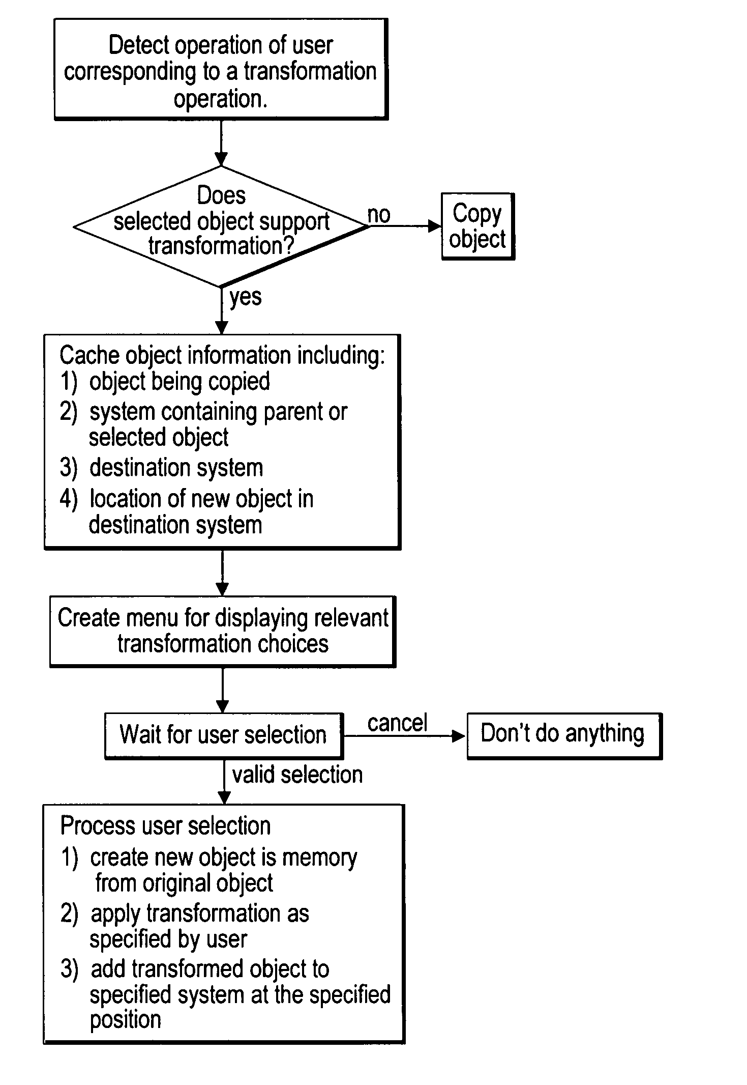
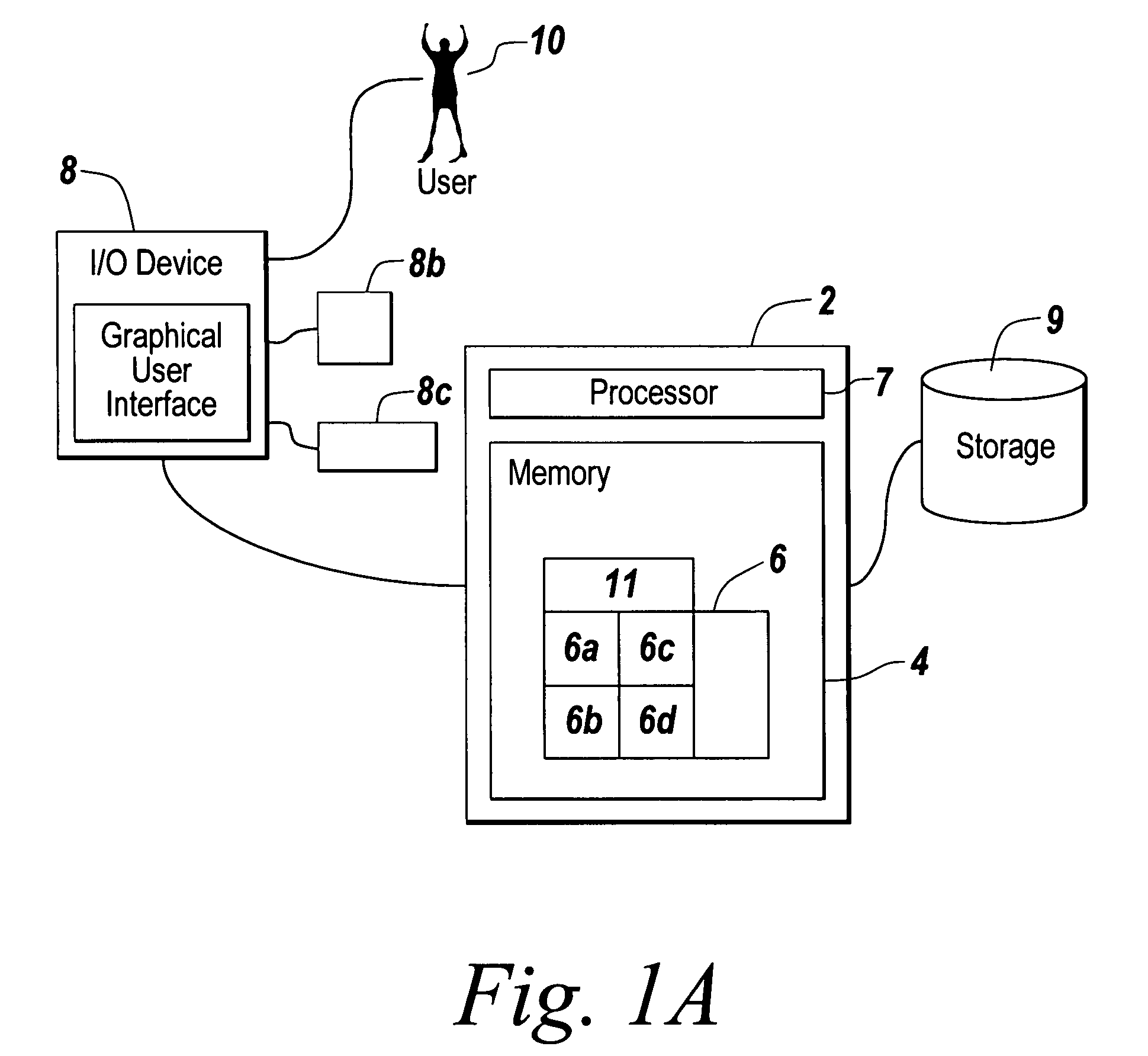
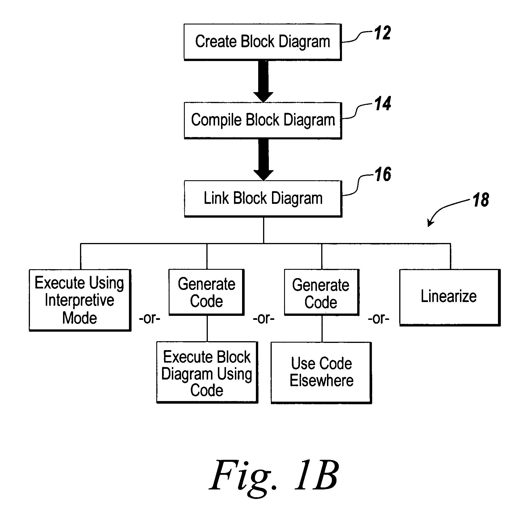
[0040]In an illustrative embodiment, the present invention provides a graphical modeling environment, such as a time-based block diagram, which enables a user to model a process easily and intuitively. The illustrative embodiment of the present invention provides an improved tool for modeling, simulating, and / or analyzing dynamic systems, which enables a user to select from several possible transformation operations when the user selects a graphical object in a block diagram. The present invention will be described below relative to an illustrative embodiment with respect to a time-based block diagram, though the invention may be implemented in any suitable graphical modeling environment. Those skilled in the art will appreciate that the present invention may be implemented in a number of different applications and embodiments and is not specifically limited in its application to the particular embodiments depicted herein.

[0041]FIG. 1A depicts an environment suitable for practicing ...


PUM


Abstract

In a graphical modeling environment, one of a selection of transformation operations is performed on a graphical object by first selecting the graphical object. A user may select a particular transformation operation to be executed on the graphical object from a list of transformation operations displayed to the user. A transformed graphical object derived from the selected graphical object may be then automatically created without retrieving the transformed graphical object from a library or other source.

Description

RELATED APPLICATIONS[0001]This application claims the benefit under 35 U.S.C. §120 as a continuation of U.S. Non-provisional application Ser. No. 10 / 699,323, filed Oct. 31, 2003, entitled “Transforming Graphical Objects in a Graphical Modeling Environment,” the entire disclosure of which is hereby incorporated by reference for all purposes.FIELD OF THE INVENTION[0002]The present invention relates to a graphical object in a software application. More particularly, the present invention relates to modifying a graphical object.BACKGROUND OF THE INVENTION[0003]Copying graphical objects is a common operation in building and using software applications. Traditional copy operations on graphical objects have resulted in creation of new objects that are clones of the original object. Each new object has the same class type and the same properties as the original object.[0004]One class of programs in which graphical object is copied is graphical modeling environments. Examples of graphical mo...

Claims


Application Information

Patent Timeline
Patent Type & Authority Patents(United States)
IPC IPC(8): G06F9/44
CPCG06F8/34
Inventor SINGH, SANJAICIOLFI, JOHN
Owner THE MATHWORKS INC
Learn More