RFID tag with double-switch rectifier

a technology of rectifier and rfid tag, which is applied in the field of rfid tags, can solve the problems of difficult energy harvesting from rf wave, and achieve the effect of maximizing the energy harvesting efficiency of the rfid tag circui

Active Publication Date: 2011-10-25
IMPINJ
View PDF15 Cites 14 Cited by
  • Summary
  • Abstract
  • Description
  • Claims
  • Application Information

AI Technical Summary

Benefits of technology

[0015]The disclosed power rectifier maximizes an energy harvest efficiency of the RFID tag circuit.

Problems solved by technology

Harvesting sufficient power from the RF wave can be difficult since the voltage of the RF signal is in the range of approximately 200 millivolts, and a typical supply voltage for circuits of the RFID tag is one volt.
Due to low available RF signal amplitude that it is insufficient to operate the circuitry needed by the RFID tag, the power rectifier circuits typically use charge-pumps to increase the output DC voltage.

Method used


Image

  • RFID tag with double-switch rectifier
  • RFID tag with double-switch rectifier
  • RFID tag with double-switch rectifier

Examples


Embodiment Construction

proceeds with reference to the accompanying Drawings, in which:

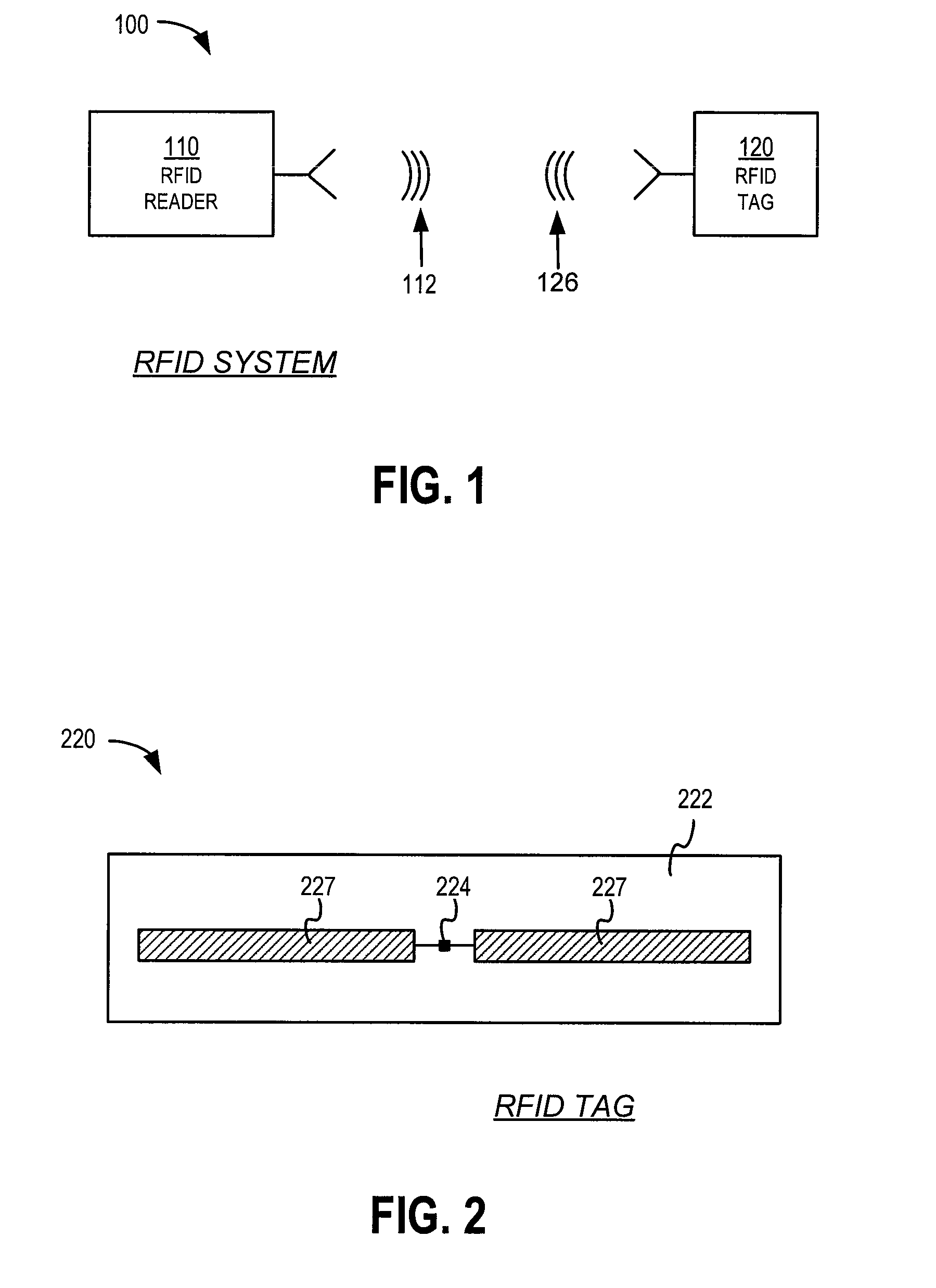
[0018]FIG. 1 is a block diagram of an RFID system.

[0019]FIG. 2 is a diagram showing components of a passive RFID tag.

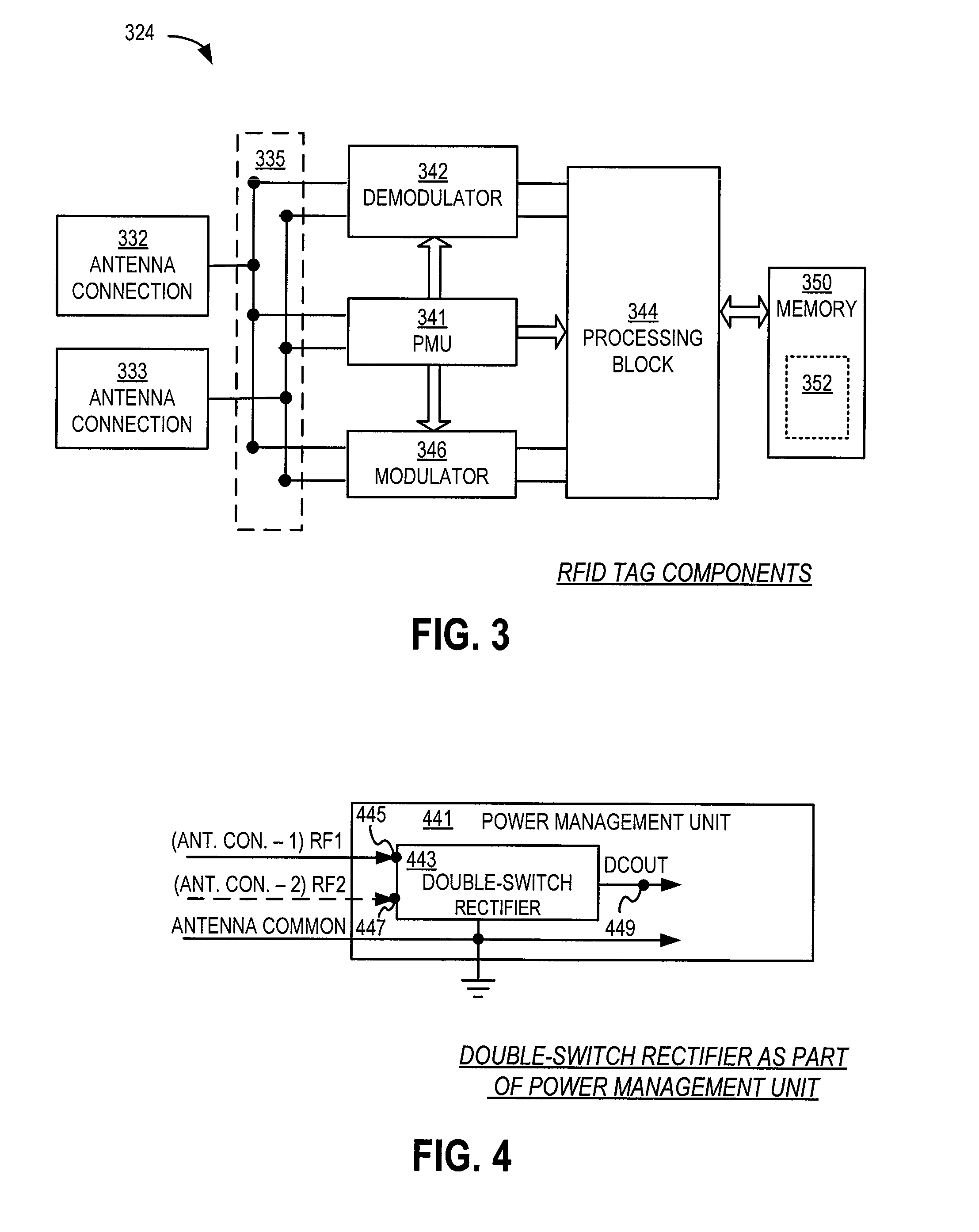
[0020]FIG. 3 is a block diagram of an implementation of an electrical circuit formed in an IC of the tag of FIG. 2.

[0021]FIG. 4 is a block diagram illustrating components of a Power Management Unit of the circuit of FIG. 3.

[0022]FIG. 5 is a schematic diagram of a conventional Dickson RF Charge-pump Stage according to prior art.

[0023]FIG. 6 is a schematic diagram of a conventional NMOS RF Rectifier Stage according to prior art.

[0024]FIG. 7 is a schematic diagram of a conventional CMOS RF Rectifier Stage according to prior art.

[0025]FIG. 8 is a schematic diagram of a single charge-pump cell according to prior art.

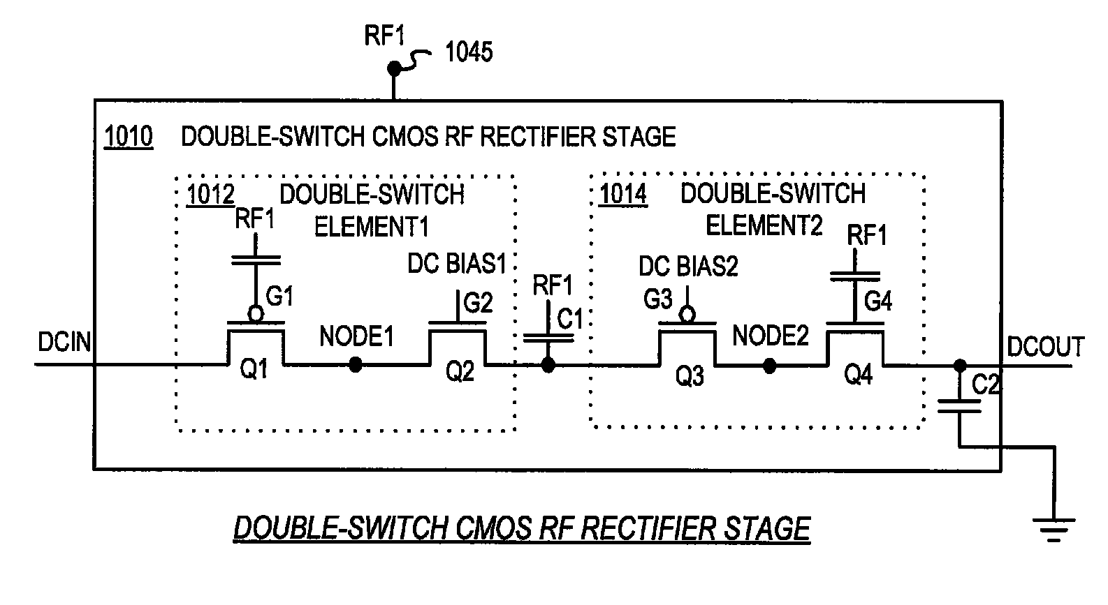
[0026]FIG. 9A is a block diagram illustrating power rectifier using Double-Switch stages in the Power Management Unit of FIG. 4 according to an embodiment.

[0027]FIG. 9B is a block diagram illustrati...


PUM


Abstract

The present disclosure provides a power rectifier for a Radio Frequency Identification tag circuit. The power rectifier is constructed from a pair of complementary MOS transistors. Gates of the transistors have predetermined voltages applied to them. The applied voltages bias the transistors to near their active operating regions, while an additional RF control signal is being applied to only one of the gates of the transistors in the complementary pair.

Description

RELATED APPLICATIONS[0001]This patent application claims priority from U.S. Provisional Patent Application Ser. No. 60 / 905,416 filed on Mar. 7, 2007, the disclosure of which is hereby incorporated by reference for all purposes.[0002]This patent application claims priority from U.S. Provisional Patent Application No. 60 / 925,920 filed on Apr. 24, 2007, the disclosure of which is hereby incorporated by reference for all purposes.[0003]This patent application claims priority from U.S. Provisional Patent Application Ser. No. 60 / 937,090 filed on Jun. 25, 2007, the disclosure of which is hereby incorporated by reference for all purposes.[0004]This patent application may be found to be pertinent to commonly owned U.S. patent application Ser. No. 12 / 042,117 and, filed on the same day as the instant application, listing the same inventors with the instant application, and entitled “RFID TAGS WITH SYNCHRONOUS POWER RECTIFIER”.FIELD OF THE INVENTION[0005]The present disclosure addresses the fie...

Claims


Application Information

Patent Timeline
Patent Type & Authority Patents(United States)
IPC IPC(8): G08B13/14
CPCG08B13/14G06K19/0709
Inventor HYDE, JOHN D.OLIVER, RONALD A.PEACH, CHARLES J. T.
Owner IMPINJ
Why Eureka
Try Eureka