
Polarization control system and display device

a control system and display device technology, applied in the direction of polarising elements, instruments, optics, etc., can solve the problem that the excellent bright state cannot be provided at a wider azimuth or viewing angle, and achieve the excellent bright state, excellent dark state, excellent dark state

Inactive Publication Date: 2011-10-11
LG ELECTRONICS INC +1
View PDF23 Cites 4 Cited by
  • Summary
  • Abstract
  • Description
  • Claims
  • Application Information

AI Technical Summary

Benefits of technology

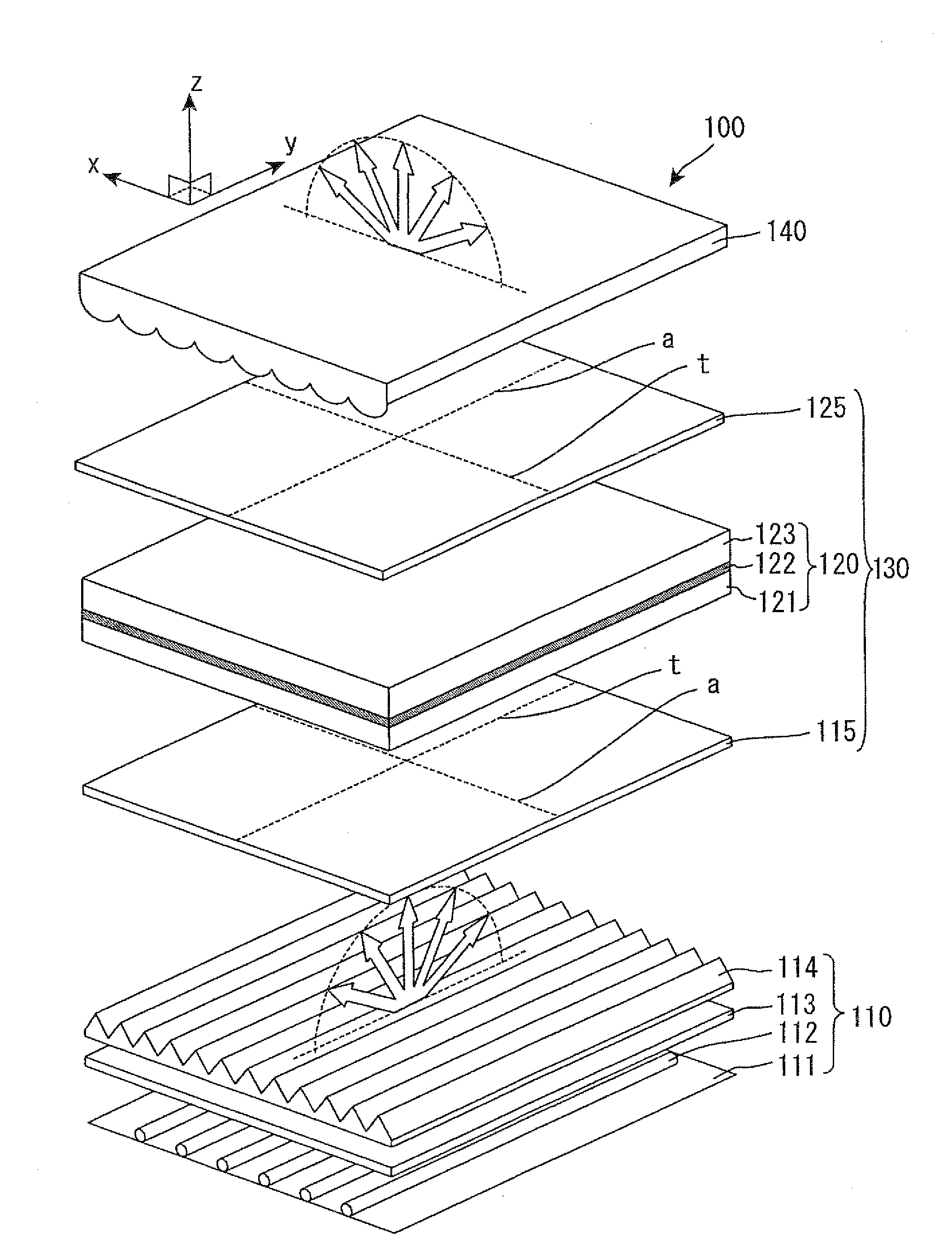
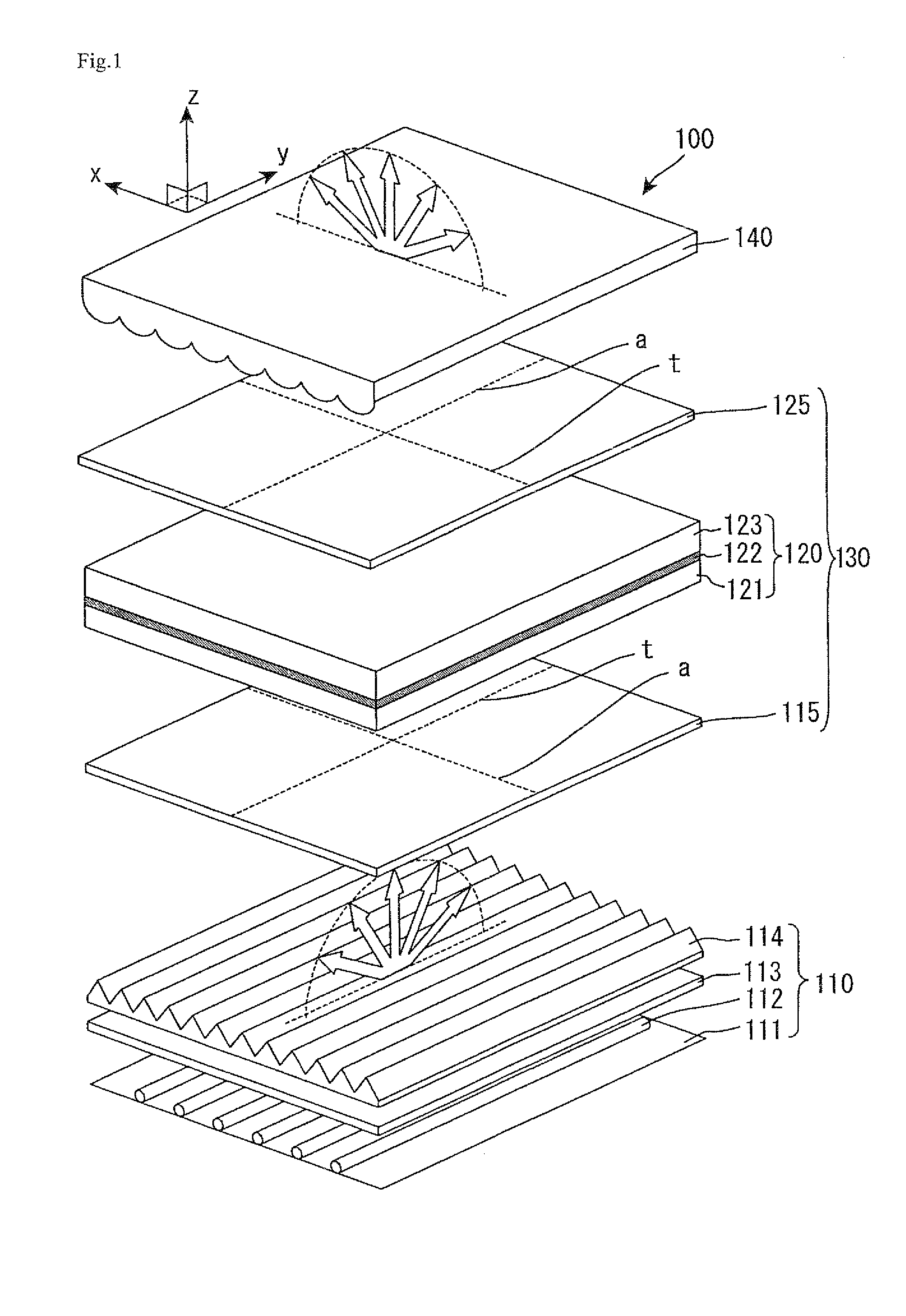
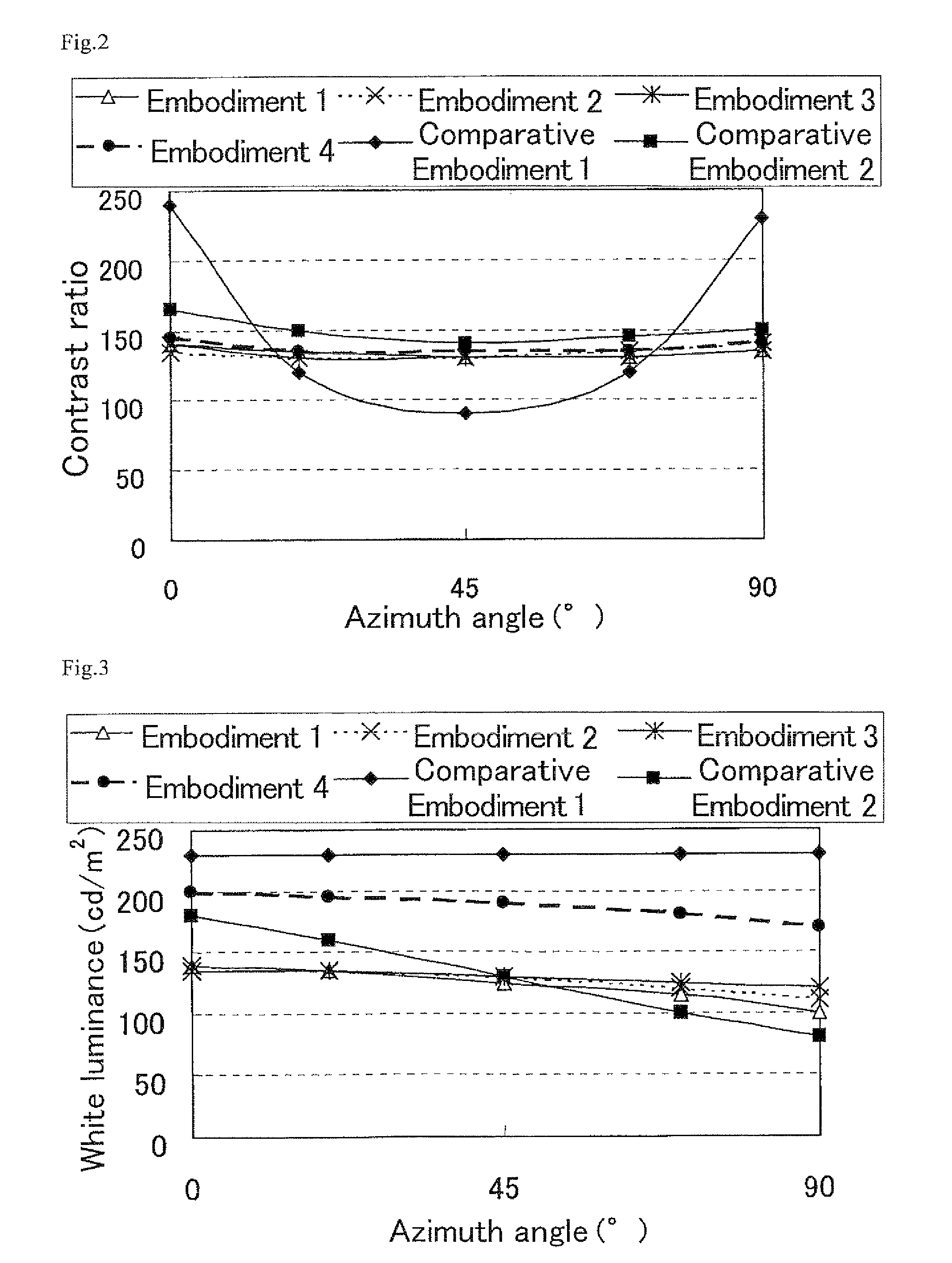
[0083]The polarization control system of the present embodiment includes an E-type polarizer and therefore can provide excellent dark state at a wide azimuth and viewing angle. Further, the polarization control system includes a viewing angle control element for controlling a traveling direction of light which has passed through the E-type polarizer and therefore can provide excellent bright state at a wide azimuth and viewing angle.

Problems solved by technology

Accordingly, excellent bright state cannot be provided at a wider azimuth or viewing angle.

Method used


Image

  • Polarization control system and display device
  • Polarization control system and display device
  • Polarization control system and display device

Examples


embodiment 1

[0097]A liquid crystal cell was prepared by separating polarizers and retardation films arranged on both sides (observation surface side and the back surface side) of a liquid crystal display panel in a commercially available liquid crystal display device in normally black VA mode (product of Sharp Corp., trade name: LC20AX-5). Then, a triacetyl cellulose film (product of FUJIFILM Corp., trade name: TD-80U) was used as a base film, and thereon, an aqueous solution of lyotropic liquid crystal containing 16.7% by weight of a dichroic pigment on the solid content basis (product of Optiva, Inc., trade name: LC polarizer) was applied on the base film to have a thickness of 4 μm with a wire bar. Then, the coated liquid was dried at 40° C. to provide an E-type polarizer. Thus-prepared E-type polarizer was arranged on the back surface side of the liquid crystal cell in such a way that the base film surface was not on the liquid crystal cell side (the coated surface is on the side of the liq...

embodiment 2

[0103]A liquid crystal display device in the present Embodiment has the same configuration as in Embodiment 1 except that the following viewing angle control element was used. A microlens array sheet (refer to Embodiment 1 in Japanese Kokai Publication No. Hei-05-249453) which includes convex lenses (material: UV-curable acrylic resin, a regular hexagonal bottom surface having a scattering intensity of 15°, and an arrangement pitch of the lenses: 64 μm) on one surface of a transparent base film (material: polyester, thickness: 188 μm), was arranged in such a way that: the surface where the convex lenses are formed is on the liquid crystal cell side and the other surface is on the observation surface side; and that a diffusion major axis azimuth of the sheet is parallel to a transmission axis azimuth in the plane of the O-type polarizer (an absorption axis azimuth in the plane of the E-type polarizer).

embodiment 3

[0104]A liquid crystal display device in the present Embodiment has the same configuration as in Embodiment 2, except that as the viewing angle control element, a light diffraction film (product of Sumitomo Chemical Co., Ltd., trade name: LUMISTY, product number: MFX-1515) was arranged in such a way that an azimuth where opaque state is observed is parallel to a transmission axis azimuth in the plane of the O-type polarizer (an absorption axis azimuth in the plane of the E-type polarizer).


PUM

PropertyMeasurementUnit
polar angleaaaaaaaaaa
azimuth anglesaaaaaaaaaa

Abstract

A polarization control system which includes an E-type polarizer and therefore can provide excellent dark state at a wide azimuth and viewing angle. Further, the polarization control system includes a viewing angle control element for controlling a traveling direction of light which has passed through the E-type polarizer and therefore can provide excellent bright state at a wide azimuth and viewing angle. Further a display device is disclosed including such a polarization control system. The polarization control system is a polarization control system including a plurality of polarizers, wherein the polarization control system includes an E-type polarizer and a viewing angle control element, and the viewing angle control element controls a traveling direction of light which has passed through the E-type polarizer.

Description

[0001]This application is the U.S. national phase of international Application No. PCT / JP2007 / 064194 filed 18 Jul. 2007 which designated the U.S. and claims priority to Japanese Patent Application No. 2006-243284 filed 7 Sep. 2006, the entire contents of each of which are hereby incorporated by reference.TECHNICAL FIELD[0002]The technology presented herein relates to a polarization control system and a display device. More specifically, the present invention relates to a polarization control system suitably used in a display device such as a liquid crystal display device and the like. The present invention further relates to a display device.BACKGROUND ART[0003]There are various types (generally, called “display mode”) of the liquid crystal display device. A display mode in which a liquid crystal cell is arranged between a pair of polarizers disposed in Cross Nicol arrangement is the most common mode. Such a liquid crystal display device provides black display by disposing a pair of...

Claims


Application Information

Patent Timeline
Patent Type & Authority Patents(United States)
IPC IPC(8): G02F1/1335G02F1/13G02B5/30
CPCG02B3/005G02B5/3033G02F1/133528G02F1/133526G02F2001/133531G02F2001/133607G02F2413/11G02F2413/12G02F1/133531G02F1/133607G02F1/133634
Inventor SAKAI, AKIRA
Owner LG ELECTRONICS INC
Learn More