Illumination system
a technology of illumination system and light source, which is applied in the direction of printing, instruments, fibre light guides, etc., can solve the problems of reducing the light utilization efficiency and brightness of projection images, and the edge blur problem of light spots, so as to increase the overfill ratio, improve the light utilization efficiency, and reduce the size
- Summary
- Abstract
- Description
- Claims
- Application Information
AI Technical Summary
Benefits of technology
Problems solved by technology
Method used
Image
Examples
first embodiment
The First Embodiment
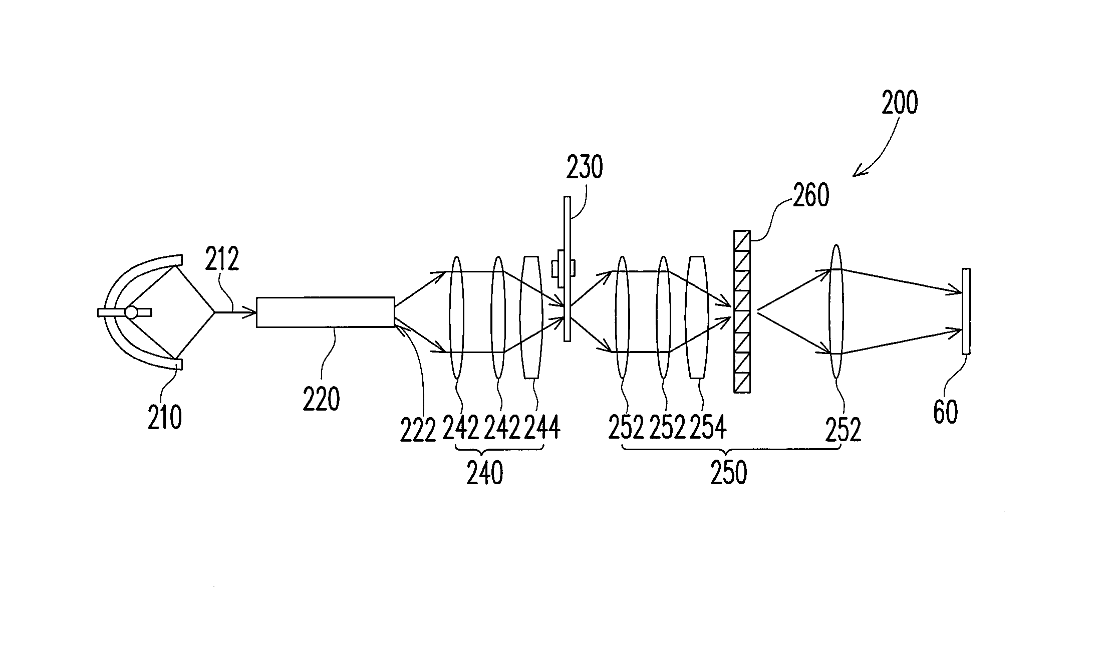
[0026]FIG. 4 is a diagram of an illumination system according to a first embodiment of the present invention. Referring to FIG. 4, an illumination system 200 of the present embodiment is for providing an illumination beam 212 to a light valve 60. The illumination system 200 includes a light source 210, a light integration rod (LIR) 220, a color wheel 230, a first focusing unit 240 and a second focusing unit 250. The light source 210 is for providing the illumination beam 212, while the LIR 220 is disposed on a transmission path of the illumination beam 212. The first focusing unit 240 is disposed between the LIR 220 and the color wheel 230, and the first focusing unit 240 is capable of focusing the illumination beam 212 onto the color wheel 230. The second focusing unit 250 is disposed between the color wheel 230 and the light valve 60, and the second focusing unit 250 is capable of focusing the illumination beam 212 onto the light valve 60.
[0027]In more detail, ...
second embodiment
The Second Embodiment
[0033]Referring to FIG. 7, an illumination system 300 according to a second embodiment of the present invention is for providing an illumination beam 312 to a light valve 60. The illumination system 300 includes a light source 310, an LIR 320, a color wheel 330 and a focusing unit 340. The light source 310 is for providing the illumination beam 312, while the LIR 320 is disposed on a transmission path of the illumination beam 312, and the section of a light output end 322 of the LIR 320 is trapezoidal. The color wheel 330 is disposed beside the light output end 322. The focusing unit 340 is disposed between the color wheel 330 and the light valve 60, and the focusing unit 340 is capable of focusing the illumination beam 312 onto the light valve 60. In more detail, the focusing unit 340 includes at least a lens 342, so as to focus the illumination beam 312 onto the light valve 60. In addition, the focusing unit 340 further includes at least an asymmetric cylindri...
third embodiment
The Third Embodiment
[0036]Referring to FIG. 8, an illumination system 400 according to a third embodiment is for providing an illumination beam 412 to a light valve 60. The illumination system 400 includes a light source 410, an LIR 420, a color wheel 430 and a focusing unit 440. The light source 410 is for providing the illumination beam 412, while the LIR 420 is disposed on a transmission path of the illumination beam 412, and the section of a light output end 422 of the LIR 420 is trapezoidal. The color wheel 430 is disposed beside the light output end 422, and the focusing unit 440 is disposed between the LIR 420 and the color wheel 430. The focusing unit 440 is capable of focusing the illumination beam 412 onto the light valve 60. In more detail, the focusing unit 440 includes at least a lens 442, so as to focus the illumination beam 412 onto the light valve 60. In addition, the illumination beam 412 is transmitted to the light valve 60 along an optical axis 412a of the illumin...
PUM
 Abstract
Description
Claims
Application Information
 - R&D
- Intellectual Property
- Life Sciences
- Materials
- Tech Scout
- Unparalleled Data Quality
- Higher Quality Content
- 60% Fewer Hallucinations
Browse by: Latest US Patents, China's latest patents, Technical Efficacy Thesaurus, Application Domain, Technology Topic, Popular Technical Reports.
© 2025 PatSnap. All rights reserved.Legal|Privacy policy|Modern Slavery Act Transparency Statement|Sitemap|About US| Contact US: help@patsnap.com


