
Arrangement for equalizing elevator rope force and elevator

a technology of elevator rope force and arrangement, which is applied in the direction of elevators, building lifts, transportation and packaging, etc., can solve the problems of large elongation, difficult to implement the required rope compensation sufficiently effectively using prior-art rope compensation devices, and large elongation, etc., to achieve large elongation or elongation of the rope, the effect of large elongation

Inactive Publication Date: 2011-09-20
KONE CORP
View PDF13 Cites 4 Cited by
  • Summary
  • Abstract
  • Description
  • Claims
  • Application Information

AI Technical Summary

Benefits of technology

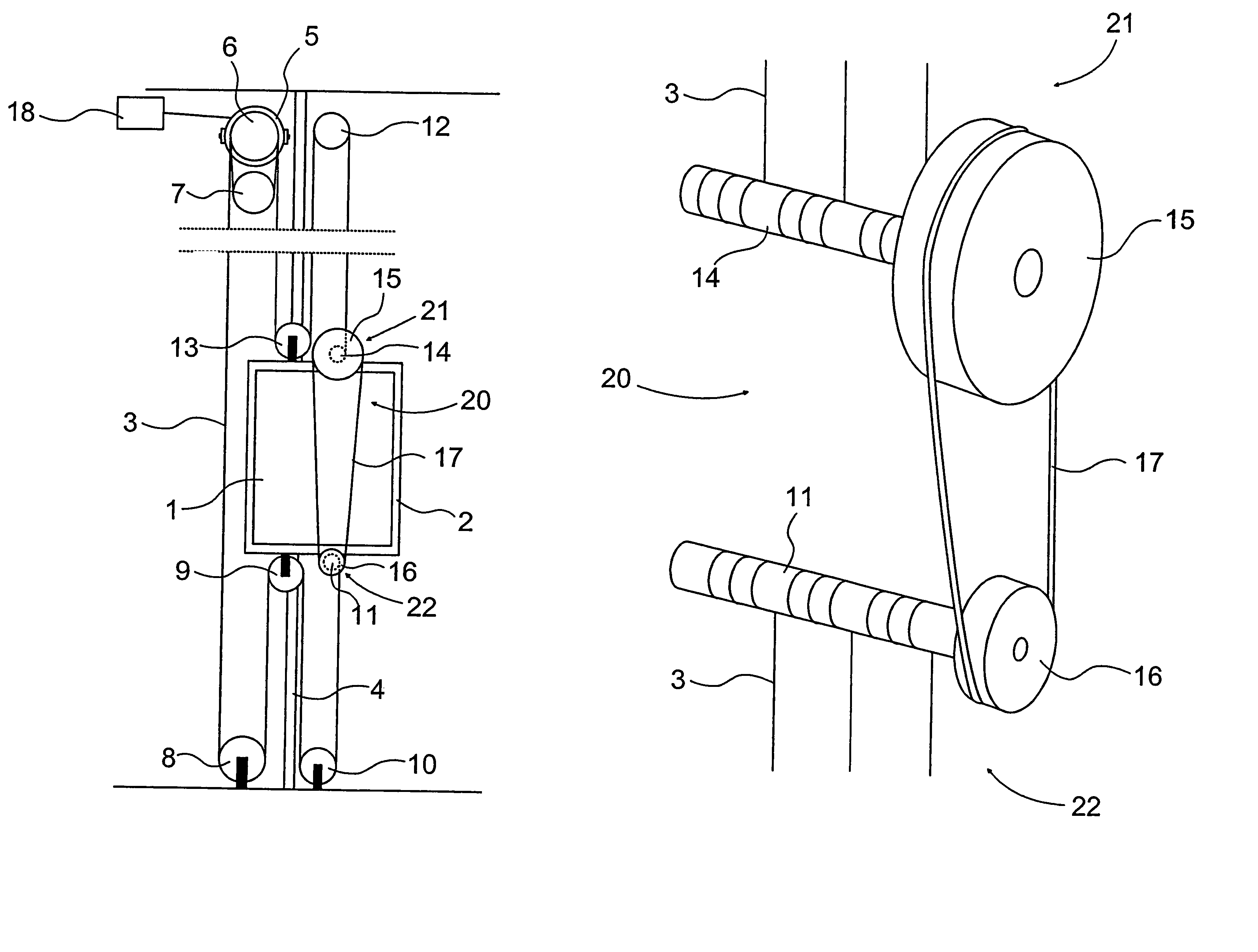
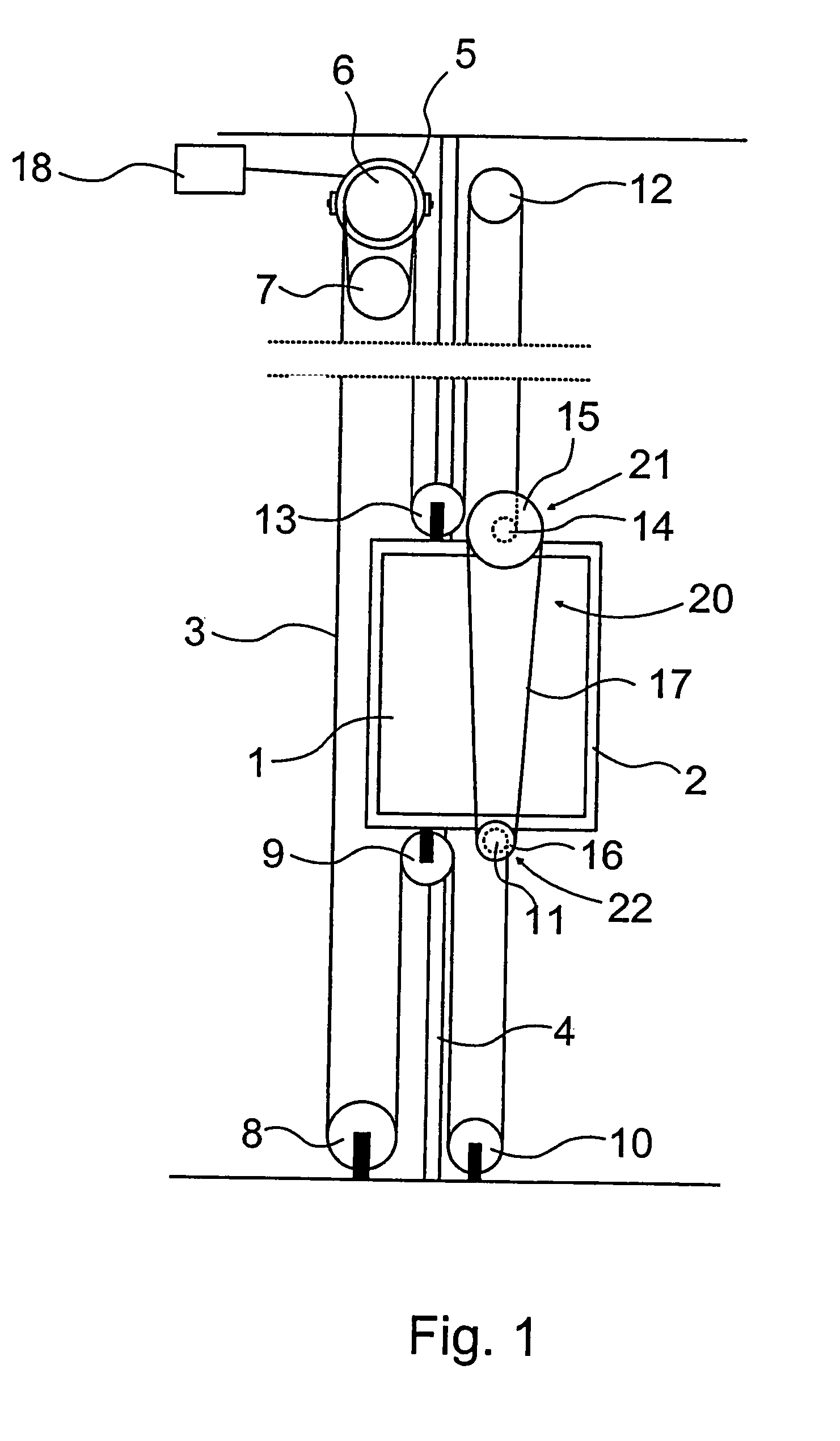
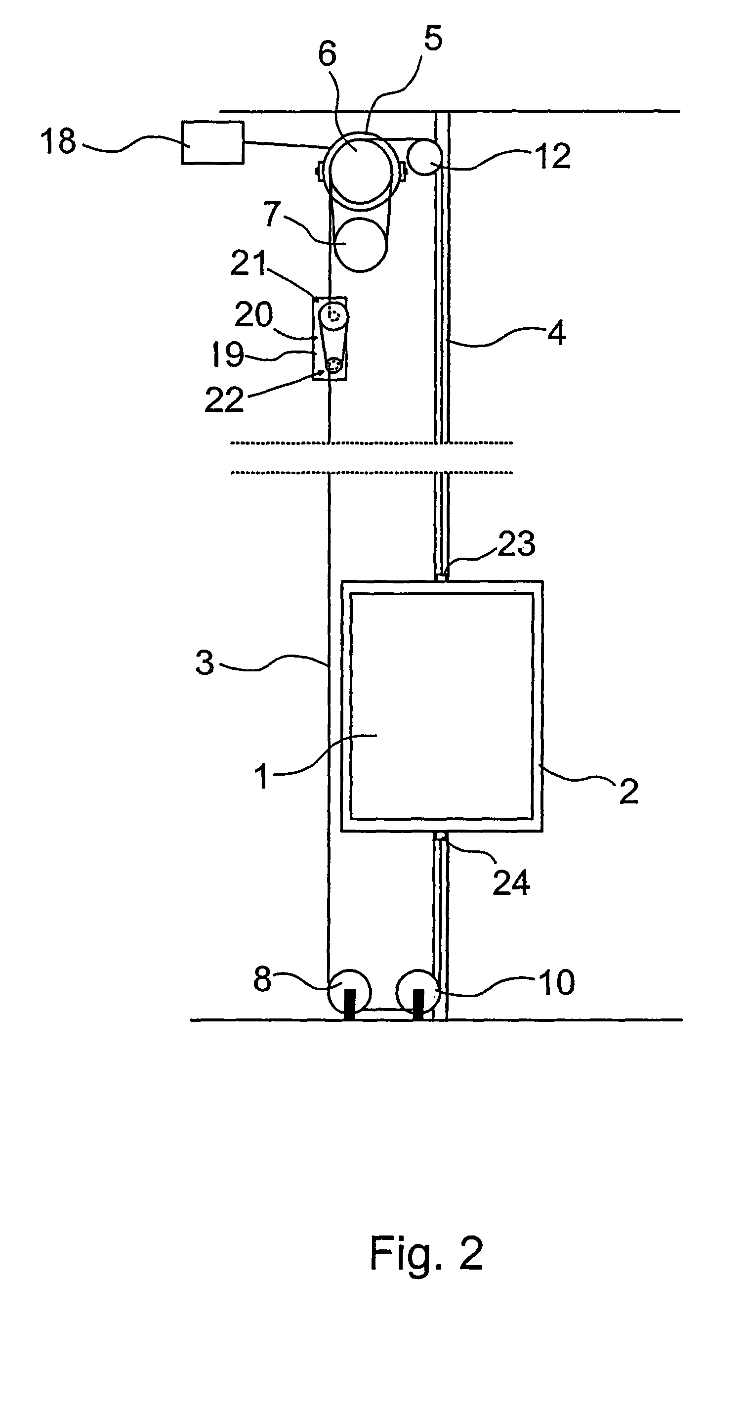
[0013]The solution of the invention has the advantage of being simple, economical, clear, versatile and effective in structure. A further advantage is that its structure allows the compensating device of the invention to be implemented as a compact component that can be placed in a small space and is thus easy to dispose in a suitable place in conjunction with other structures of the elevator, depending on the rope transmission. An additional advantage is that, when the compensating device of the invention is used, an adjustment distance of several turns can be easily provided at the end of the hoisting ropes, which allows even very large rope elongations to be compensated, so that it is possible to build elevators without counterweight having long hoisting ropes and therefore also large rope elongations or rope springing. By varying the magnitude and mutual ratio of the diameters of the transmission pulleys of the compensating device, it is possible to adjust the magnitude of the rope elongation to be compensated and the ratio between the rope forces acting on the traction sheave that can be standardized by the arrangement in question. Yet another advantage is that the suspension points can be easily disposed in a desired place and the suspension can be implemented e.g. in a centered manner as seen from above the elevator car, without any special extra functions. This is very important e.g. in the case of 1:1 suspension.

Problems solved by technology

This generally involves the problem that, due to the many rope loops used, hoisting ropes of great length are required.
Due to the length of the adjustment distance, it is difficult to implement the required rope compensation sufficiently effectively using prior-art rope compensation devices.
In such structures, large elongations produce problems already starting from 1:1 suspension.
However, a problem with such solutions is the required length of adjustment distance, because the substantially short displacement of the spring or lever does not allow a large adjustment distance and consequently does not permit compensation of large elongations.
This involves at least the problem that, in the case of large suspension ratios or when long hoisting ropes are otherwise used in tall buildings, equalization of rope forces is not possible because of the length of the adjustment distance.
As is known, such compensating sheaves have been used for this purpose, but they also involve certain problems.
One of the problems is e.g. the fact that, due to its size, the fastening of the end of the hoisting rope on the compensating sheave takes up a large space.
This would lead to the problem of having a complicated, large and heavy compensating sheave that is difficult to dispose in a suitable place in conjunction with other structures of the elevator.
Additionally, even when compensating sheaves are used, the adjustment distance is relatively short, and thus no very large elongations can be compensated.

Method used


Image

  • Arrangement for equalizing elevator rope force and elevator
  • Arrangement for equalizing elevator rope force and elevator
  • Arrangement for equalizing elevator rope force and elevator

Examples


Embodiment Construction

[0018]FIGS. 1 and 2 present simplified and diagrammatic side views of two typical traction sheave elevators in which the invention can be applied. The elevator is preferably an elevator without machine room, in which elevator the hoisting machine 5, provided with a control unit 18, together with the traction sheave 6 is mounted in the elevator shaft. The elevator type represented by each one of these figures is a traction sheave elevator with machine room above, wherein an elevator car 1 fitted inside a car frame 2 is suspended on a set of hoisting ropes 3 and the elevator car 1 is adapted to move back and forth in the elevator shaft along guide rails 4 in a substantially vertical direction. The elevator receives its hoisting power from the hoisting machine 5 by virtue of the friction between the traction sheave 6 and the hoisting ropes 3.

[0019]In the solution according to FIG. 1, the hoisting ropes 3 are secured by their first end to a reel which is mounted on the upper part of the...


PUM


Abstract

An arrangement for equalizing rope force of an elevator may include: a hoisting machine, set of hoisting ropes, traction sheave, elevator car, guide rails, and compensating device. The hoisting machine may engage the hoisting ropes via the traction sheave. The elevator car may be at least partially supported by the hoisting ropes to move the elevator car. The elevator car may move along the guide rails. The compensating device may include first and second tensioning devices. The first tensioning device may be spaced apart from the second tensioning device. The first and second tensioning devices may be interconnected via a transmission device that transmits rotary motion. A first end of the set of hoisting ropes may be secured to a point in conjunction with the first tensioning device. A second end of the set of hoisting ropes may be secured to a point in conjunction with the second tensioning device.

Description

CROSS-REFERENCE TO RELATED APPLICATIONS[0001]This application is a continuation of PCT / FI2007 / 000088 filed on Apr. 10, 2007, which is an international application claiming priority from FI 20060348 filed Apr. 10, 2006, the entire contents of which are hereby incorporated by reference.BACKGROUND[0002]1. Field[0003]The present invention relates to an arrangement for equalizing the rope force of an elevator. The invention also relates to an elevator.[0004]2. Description of Related Art[0005]It is becoming increasingly common to use large suspension ratios, e.g. 3:1 . . . 9:1 and even larger, in traction sheave elevators. This generally involves the problem that, due to the many rope loops used, hoisting ropes of great length are required. For the operation and safety of the elevator, it is essential that the hoisting rope portion of the hoisting ropes below the elevator car be kept sufficiently tightly tensioned, and thus the amount of rope elongation to be compensated, or equalized, is...

Claims


Application Information

Patent Timeline
Patent Type & Authority Patents(United States)
IPC IPC(8): B66B7/10B66B11/08
CPCB66B7/10B66B11/007B66B7/06B66B11/008
Inventor MUSTALAHTI, JORMAAULANKO, ESKORANTANEN, PEKKA
Owner KONE CORP
Learn More