
Anterior implant for the spine

anterior plate technology, applied in the field of anterior plate, can solve the problems of increasing plate size, affecting the stability of the patient's spine, and less desirable in certain situations, and achieve the effect of stabilizing the patient's spin

Inactive Publication Date: 2011-09-13
WARSAW ORTHOPEDIC INC
View PDF128 Cites 16 Cited by
  • Summary
  • Abstract
  • Description
  • Claims
  • Application Information

AI Technical Summary

Benefits of technology

The slide mechanism effectively locks screws in place, preventing migration while maintaining a compact implant size, enhancing the stability and reducing the size increase associated with traditional locking elements.

Problems solved by technology

On the other hand, the long bicortical screws, while less likely to unscrew, have other limitations making them less desirable in certain situations.
While there are thin cervical plates without a locking element, the addition of an existing locking element to a given plate design typically results in an increase in plate size, such as the plate's thickness.

Method used


Image

  • Anterior implant for the spine
  • Anterior implant for the spine
  • Anterior implant for the spine

Examples


Embodiment Construction

[0019]For the purposes of promoting an understanding of the principles of the invention, reference will now be made to the embodiments illustrated in the drawings and specific language will be used to describe the same. It will nevertheless be understood that no limitation of the scope of the invention is intended. Any alterations and further modifications in the illustrated or described embodiments, and any further applications of the principles of the invention as described or illustrated therein being contemplated as would normally occur to one skilled in the art to which the invention relates.

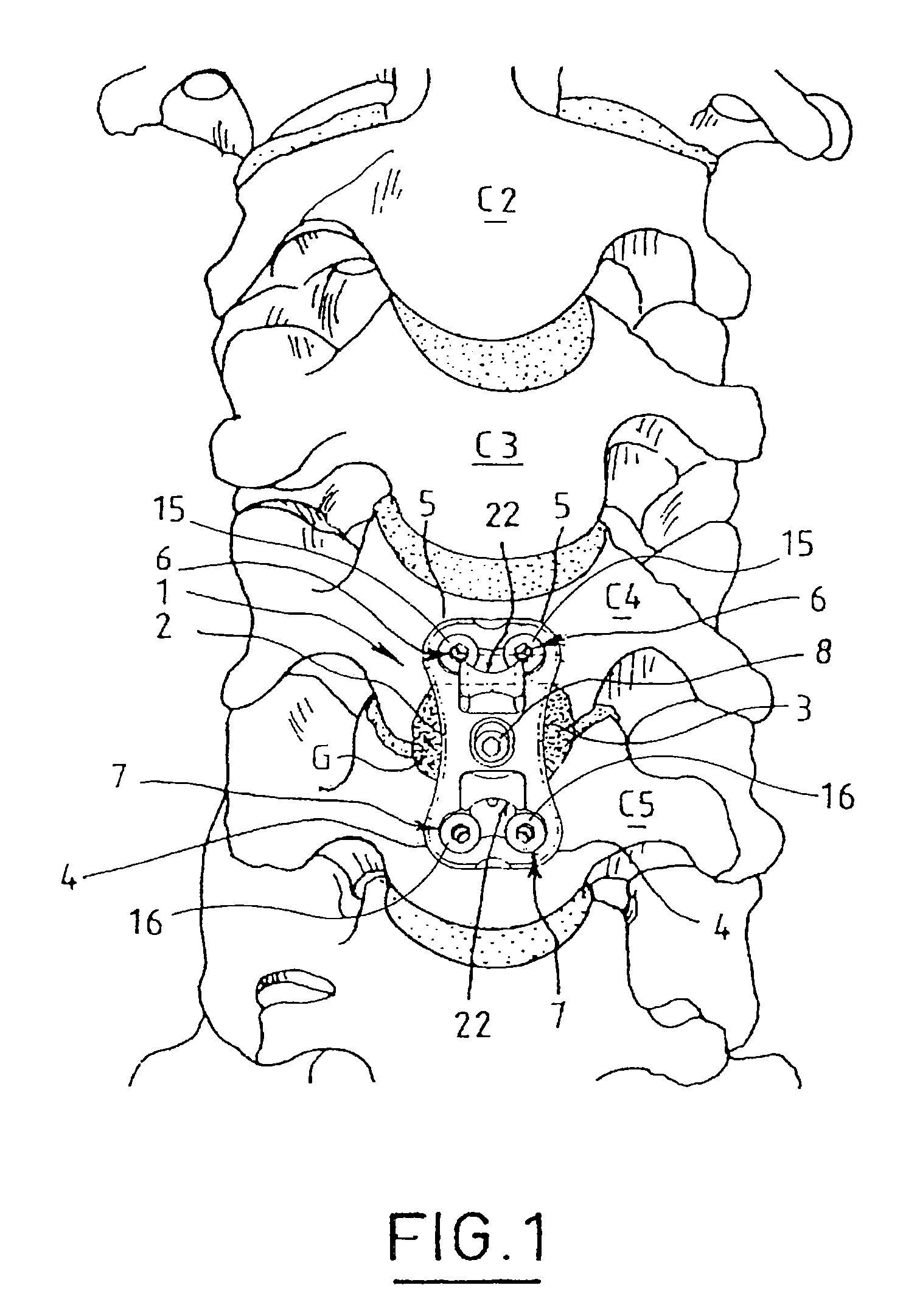
[0020]Shown in FIG. 1 is a cervical spine segment C2, C3, C4, C5, and between the vertebrae C4 and C5 (more usually C4 and C5) of which a bone graft G (partially visible) is disposed, this graft G being covered by an anterior plate 1 whose function is to stabilize the spine and to maintain this bone graft G in position.

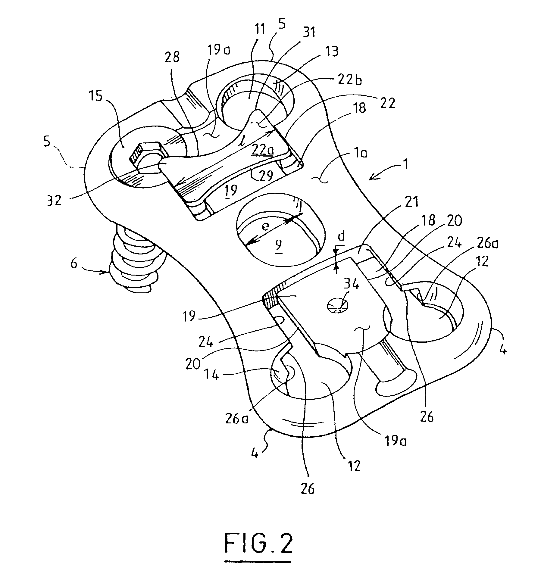
[0021]Referring additionally to FIG. 2, the plate 1 has an elongate shap...


PUM


Abstract

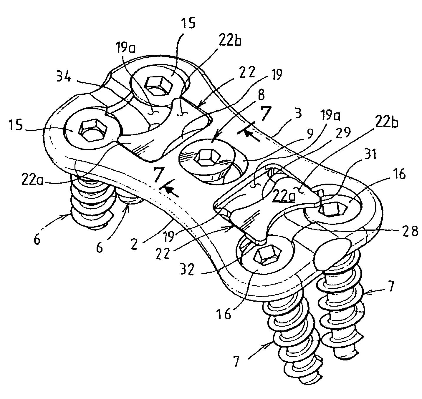
Implant for the cervical spine comprising an anterior plate (1) for maintaining a bone graft, bone anchorage screws (6,7,8) for the plate and means (22) for blocking the screws and preventing any migration of the screws, characterized in that the blocking means comprises at least one slide (22) slidably mounted on the plate so as to be applicable on at lease one anchorage screw head (15,16). The slide cooperates with means (33,34) for retaining the slide on the head of the screw. The slide may be formed by a thin platelet (22a) which is provided with lateral flanges (25) and is slidable in a complementary cavity (18) provided in the plate (1) while being flush with the surface of the plate (1). The plate (1) includes ramps (26) for retaining the slide (22) on which the flanges (25) are slidable, the slide (22) being slidable to a position in which it at least partly overlaps the heads of the associated screws (6 or 7) and is locked in position by suitable means.

Description

CROSS-REFERENCE TO RELATED APPLICATIONS[0001]The present application is a continuation of U.S. application Ser. No. 10 / 693,604, filed Oct. 27, 2003, which is a continuation of U.S. application Ser. No. 09 / 692,894, filed Oct. 20, 2000, now U.S. Pat. No. 6,652,525, which is a continuation of International Patent Application Number PCT / IB99 / 00794, filed Apr. 30, 1999, all of which are hereby incorporated by reference in their entirety.TECHNICAL FIELD[0002]The present invention relates to an implant for the spine, and more particularly, but not exclusively relates to an anterior plate for maintaining a bone graft, bone anchorage screws for the plate and means for blocking the screws and preventing any migration of the latter.BACKGROUND[0003]Spinal plates may be introduced from the anterior to stabilize the cervical spine and maintain in position or secure a bone graft which fills the spaces left by the extraction of at least one vertebral disc and, possibly, part of a contiguous cervica...

Claims


Application Information

Patent Timeline
Patent Type & Authority Patents(United States)
IPC IPC(8): A61B17/80A61B17/58A61B17/70
CPCA61B17/7059A61B17/8042
Inventor ASSAKER, RICHARDMINFELDE, RICHARD-LAURENTD'AMORE, JEAN-FRANCOIS
Owner WARSAW ORTHOPEDIC INC
Learn More