Electrical device, particularly for driving a motively and/or regeneratively operable electric machine

a technology of electric machines and electric devices, which is applied in the direction of electrical apparatus construction details, indirect heat exchangers, lighting and heating apparatus, etc., can solve the problem that electric conductors take up a relatively large amount of space, and achieve the effect of better utilization of space requirements

Active Publication Date: 2011-09-06
ROBERT BOSCH GMBH
View PDF26 Cites 4 Cited by
  • Summary
  • Abstract
  • Description
  • Claims
  • Application Information

AI Technical Summary

Benefits of technology

[0003]The electrical device of the exemplary embodiments and / or exemplary methods of the present invention, particularly for driving a motively and / or regeneratively operable electric machine, having at least one switching-element module which may be provided for inverting and / or rectifying electric voltages, and the switching-element module being able to be cooled by a cooling device on which it at least indirectly rests, is advantageously characterized in that a fixation element, at least one conductor as well as the switching-element module and the cooling device are disposed one above the other. Advantageously, the area used in one plane can thereby turn out to be considerably less, and therefore the space requirements can be better utilized, quite especially in a motor vehicle in which there is relatively little space available as it is.
[0005]If the at least one conductor is electrically isolated from the fixation element by at least one insulating intermediate layer, it is then possible, for example, to connect the fixation element to the electrical ground, regardless of the potential state of the conductor. If insulating intermediate layers between the individual conductors are formed at least sectionally in such a way that they project beyond the conductors, then it is possible to greatly increase a “creeping-current spacing” via these intermediate layers. Short circuits or power-diminishing creeping currents are thereby avoided.
[0006]A good relative-position allocation between the insulating intermediate layer and / or a conductor with respect to the fixation element results if the position is determined by a centering arrangement.
[0007]It is advantageously provided that the fixation element is produced from the same material as the housing, that is, the cooling device of the electrical device. The result is that thermal stresses between a composite construction of the fixation element, conductor, switching-element module and cooling device are largely avoided, since the fixation element, as well as the material of the housing expand with the same coefficient of thermal expansion.
[0008]To avoid edge pressures and other unacceptably high pressures between the fixation element and the switching-element module, an elastic module is provided between the fixation element and the switching-element module.
[0009]The switching-element module has both conductors which conduct high currents, as well as conductors which conduct low currents. These high-current conductors heat up more than the other “signal conductors.” It is therefore envisaged to spatially separate the high-current conductors from the signal conductors, and thus to provide that power conductors (high-current conductors) project from one side, and signal conductors project from one side. A suitable design is yielded if the sides lie opposite each other. In addition, the ends of the power conductors point away from the cooling device. This has the advantage that a junction between the conductors on the switching-element module and the power conductors is particularly conveniently accessible. Moreover, the ends of the signal conductors point away from the cooling device. For example, it is thereby possible to also mount a printed circuit board over the assemblage of switching-element module, fixation element, conductor and cooling device already mentioned. This printed circuit board may then be joined to the signal conductors by simple placement in the direction of the components just mentioned.

Problems solved by technology

In this design, it is disadvantageous that the electrical conductors take up a relatively great amount of space.

Method used


Image

  • Electrical device, particularly for driving a motively and/or regeneratively operable electric machine
  • Electrical device, particularly for driving a motively and/or regeneratively operable electric machine
  • Electrical device, particularly for driving a motively and/or regeneratively operable electric machine

Examples


Embodiment Construction

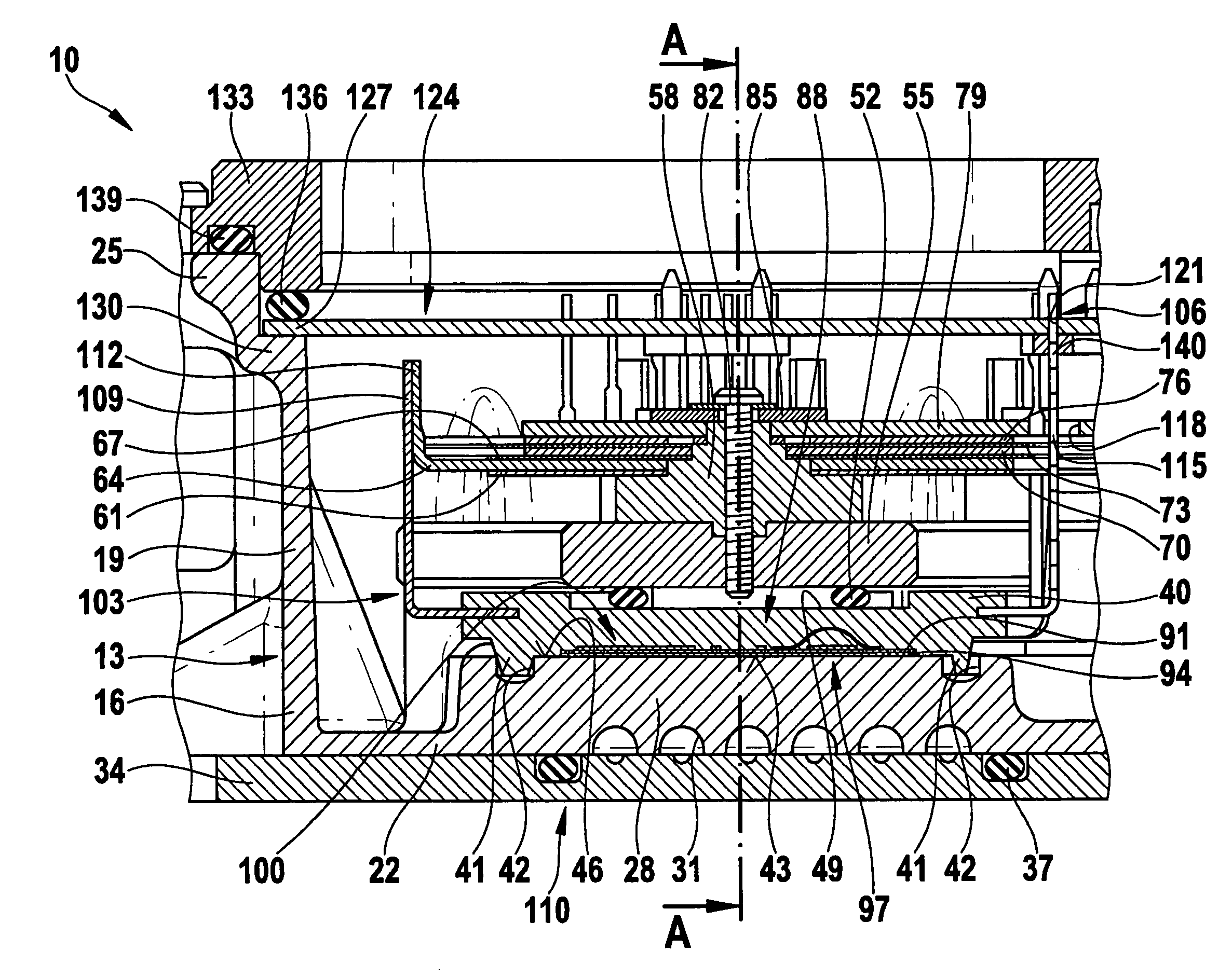
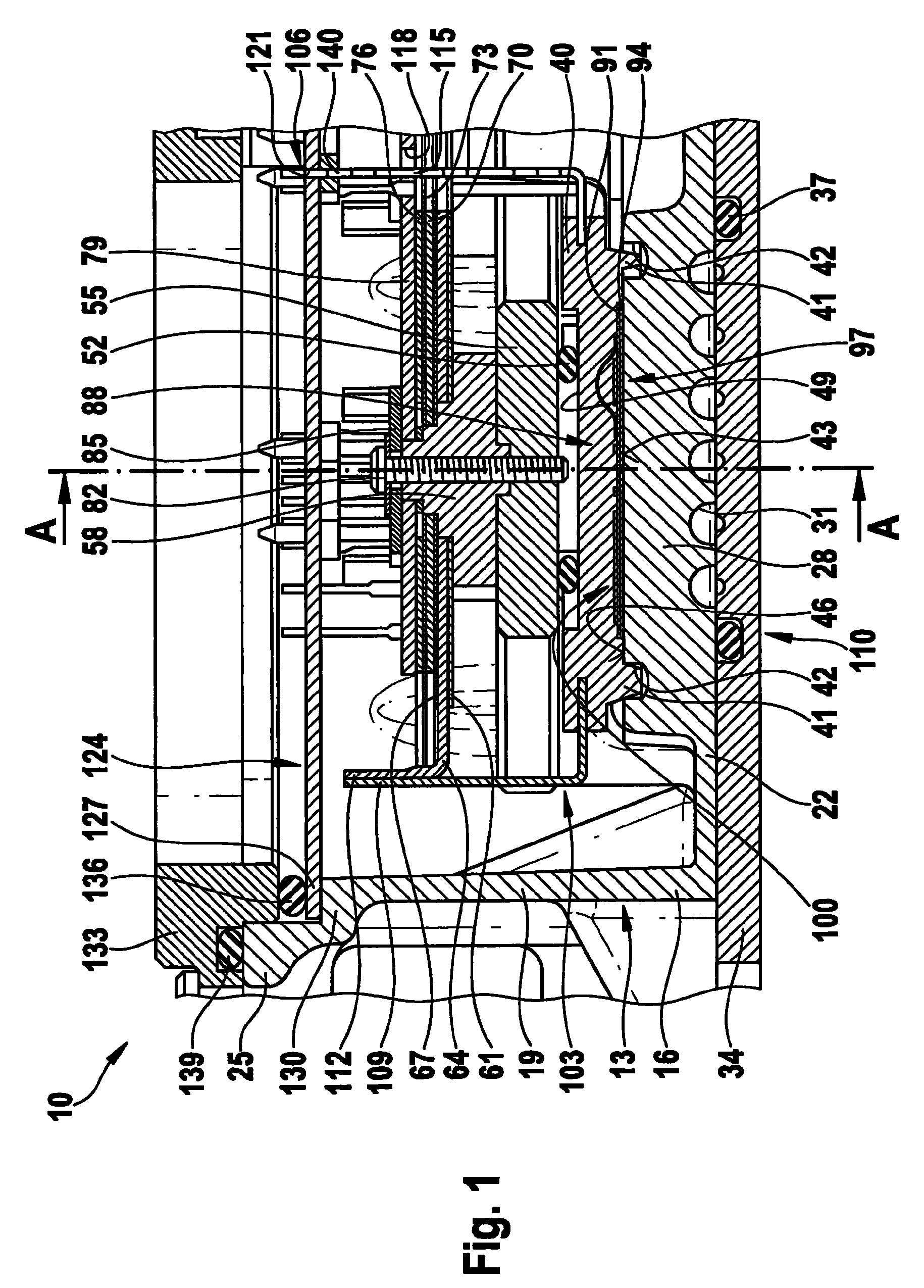
[0019]FIG. 1 shows a partial cross-section through an electrical device 10, which is used here for driving a motively and / or regeneratively operable electric machine (not shown). This electrical device 10 is made up of a housing 13, which is structured from a plurality of components. Housing 13 is made of a cup-shaped housing part 16, in which various electrical and electronic components are disposed, which will be discussed later. Cup-shaped housing part 16 has a housing wall 19 which ends in a housing edge 25 facing away from a housing bottom 22. Housing bottom 22 has a housing section, denoted here as platform 28, whose material thickness is somewhat greater. On its side facing away from the bottom floor of housing 13, this platform 28 has a plurality of cooling channels 31 that are closed by a closing cover 34. Cooling channels 31 are closed on the whole in fluid-tight manner by a seal 37. Initially, a switching-element module 40 sits on this platform 28 and in housing 13.

[0020]...


PUM


Abstract

An electrical device, particularly for driving a motively and / or regeneratively operable electric machine, having at least one switching-element module, which may be for inverting and / or rectifying electric currents, the switching-element module being able to be cooled by a cooling device and resting at least indirectly thereon, a fixation element, at least one conductor, as well as the switching-element module and cooling device being disposed one above the other.

Description

FIELD OF THE INVENTION[0001]The present invention relates to an electrical device for driving a motively and / or regeneratively operable electric machine.BACKGROUND INFORMATION[0002]The U.S. Patent 2004 / 0062005 A1 discusses a power converter which is used to drive electric industrial motors. This device has circuit modules which are disposed on a heat sink. In addition to the circuit modules, electrical conductors are also provided. In this design, it is disadvantageous that the electrical conductors take up a relatively great amount of space.SUMMARY OF THE INVENTION[0003]The electrical device of the exemplary embodiments and / or exemplary methods of the present invention, particularly for driving a motively and / or regeneratively operable electric machine, having at least one switching-element module which may be provided for inverting and / or rectifying electric voltages, and the switching-element module being able to be cooled by a cooling device on which it at least indirectly rests...

Claims


Application Information

Patent Timeline
Patent Type & Authority Patents(United States)
IPC IPC(8): H05K7/20
CPCH02M7/003H05K7/20927H02K9/24H02M7/00H05K7/20
Inventor JERG, JUERGENILIC, ERICHKIENLE, WOLFRAMSAUR, DIETMAR
Owner ROBERT BOSCH GMBH
Why Eureka
Try Eureka