Fishing reel handle assembly

a technology of handle assembly and fishing reel, which is applied in the direction of fishing, instruments, controlling members, etc., can solve the problems of difficulty in aligning the orientation of the handle knobs in parallel to the handle shaft, and achieve the effect of enhanced rotational balance of the fishing reel handle assembly and easy attachmen

Inactive Publication Date: 2011-09-06
SHIMANO COMPONENTS MALAYSIA
View PDF17 Cites 4 Cited by
  • Summary
  • Abstract
  • Description
  • Claims
  • Application Information

AI Technical Summary

Benefits of technology

[0015]A fishing reel handle assembly according to a third aspect relates to the fishing reel handle assembly according to the second aspect, and the reel handle assembly further includes a weight member. The weight member includes at least one non-circular shaft on a base end thereof. The weight member is also configured to be engaged with at least either of the non-circular recesses of the first and second attachment portions. When the fishing reel handle assembly is herein used as the single-handle assembly, the weight member can be attached to one of the first and second attachment portions to which the handle arm is not attached. Therefore, the rotational balance of the fishing reel handle assembly will be enhanced even if the fishing reel handle assembly is used as the single-handle assembly.
[0016]A fishing reel handle assembly according to a fourth aspect relates to the fishing reel handle assembly according to one of the second and third aspects, and the fishing reel handle assembly further includes first and second screw members. The first and second screw members are inserted into the first and second attachment portions along handle attachment directions intersecting the first and second axes, respectively. The first and second screw members are further screwed into the base ends of the first and second handle arms, respectively. According to the fourth aspect, the first and second handle arms are secured to the first and second attachment portions by the first and second screw members, respectively. With this structure, the first and second handle arms can be easily attached to or detached from the first and second attachment portions, respectively.
[0020]A seventh aspect relates to a fishing reel handle assembly. The fishing reel handle assembly includes a handle shaft, handle knobs, first and second handle arms, and an arm attachment. The handle knobs are rotatably attached to front ends of the first and second handle arms, respectively. The arm attachment is configured to rotate integrally with the handle shaft. The arm attachment includes first and second attachment portions. The first attachment portion is irremovably attached to the first handle arm. The first attachment portion arranges the first handle arm along a first axis intersecting the axis of the handle shaft. The second attachment portion allows a base end of the other of the first and second handle arms to be detachably attached thereto. The second attachment portion also prevents the base end of the other of the first and second handle arms from rotating about a second axis opposed to the first axis across the handle shaft.

Problems solved by technology

The structure makes it difficult to align orientations of the handle knobs in parallel to the handle shaft when the handle arm is attached to the arm attachment.

Method used


Image

  • Fishing reel handle assembly
  • Fishing reel handle assembly
  • Fishing reel handle assembly

Examples


Embodiment Construction

[0034]Selected embodiments will now be explained with reference to the drawings. It will be apparent to those skilled in the art from this disclosure that the following descriptions of the embodiments are provided for illustration only and not for the purpose of limiting the invention as defined by the appended claims and their equivalents.

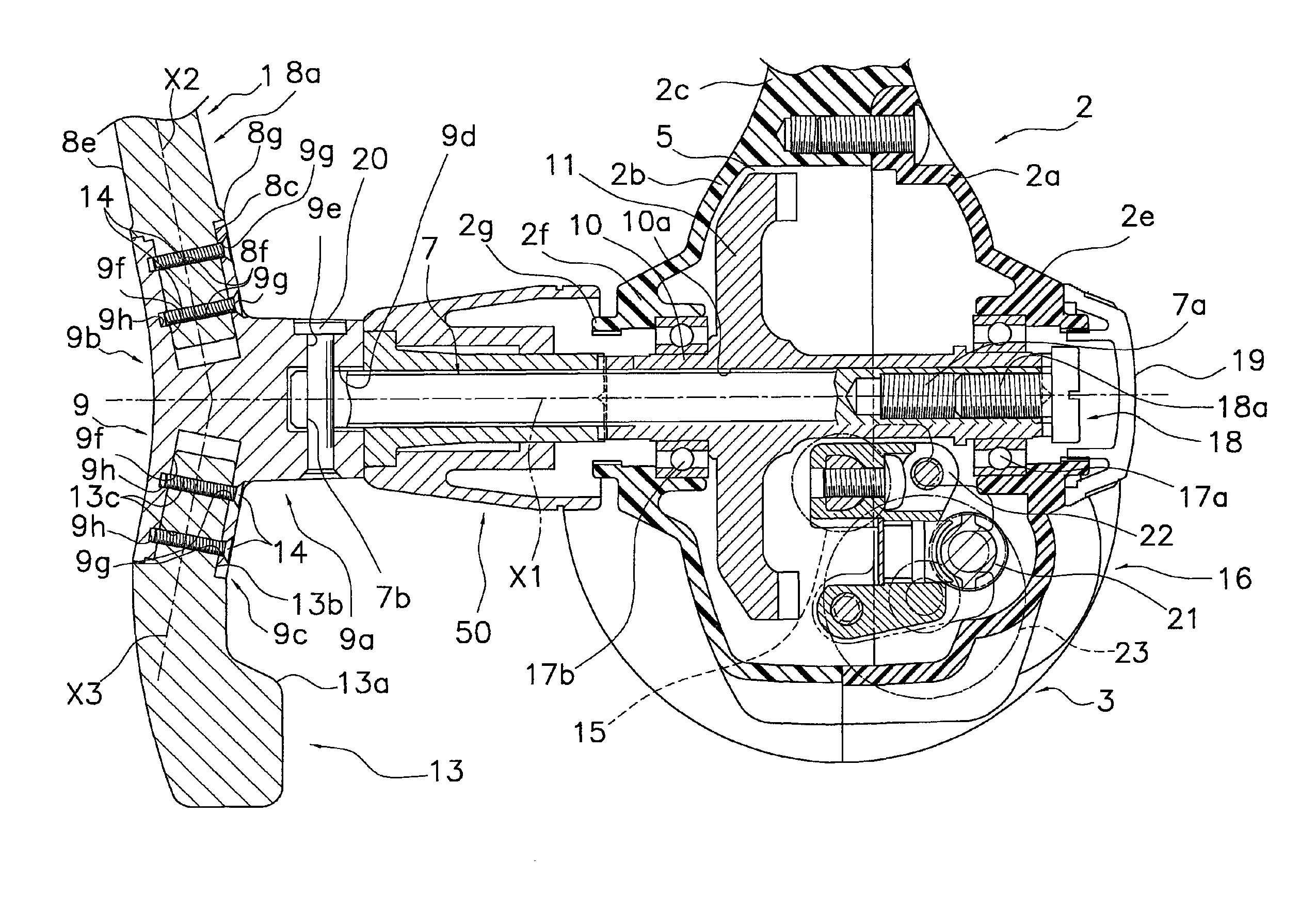
[0035]As illustrated in FIGS. 1 and 2, a spinning reel, in accordance with an exemplary embodiment, includes a handle assembly 1, a reel unit 2, a rotor 3 and a spool 4. The reel unit 2 rotatably supports the handle assembly 1. The rotor 3 winds a fishing line around the spool 4. The rotor 3 is rotatably supported by the front part of the reel unit 2. The spool 4 winds the fishing line onto its outer peripheral surface. The spool 4 is disposed in front of the rotor 3 while being reciprocatable back and forth. Note the handle assembly 1 is allowed to be attached either a left side (see FIGS. 1 and 2) of the reel unit 2 or a right side (not illustra...


PUM


Abstract

A fishing reel handle assembly has a handle shaft, handle knobs, first and second handle arms, and an arm attachment. The handle knobs are respectively rotatably attached to the attachment ends of the first and second handle arms. The arm attachment is configured to rotate integrally with the handle shaft. The arm attachment includes a first attachment portion that allows the base end of the first handle arm to be detachably attached to the first attachment portion. The first attachment portion prevents the base end of the first handle arm from rotating about a first axis. The second attachment portion allows the base end of the second handle arm to be detachably attached to the second attachment portion. The second attachment portion prevents the base end of the second handle arm from rotating about a second axis.

Description

CROSS-REFERENCE TO RELATED APPLICATIONS[0001]This application claims priority to Japanese Patent Application No. 2009-130738 filed on May 29, 2009, the entirety of which is hereby incorporated by reference in its entirety.BACKGROUND[0002]1. Field of the Invention[0003]The present invention relates to a handle assembly, particularly to a fishing reel handle assembly configured to rotate integrally with a handle shaft of the fishing reel.[0004]2. Background Information[0005]In a fishing reel (e.g., the spinning reel and the dual-bearing reel), a handle assembly is rotatably attached to a reel body in order to rotate a rotor or a spool. The fishing reel handle assembly includes a handle knob and a handle arm configured to rotate integrally with a handle shaft. The handle assembly is classified into either a double-handle assembly or a single-handle assembly. In the double-handle assembly, a handle shaft is attached to the intermediate part of a handle arm whereas handle knobs are attac...

Claims


Application Information

Patent Timeline
Patent Type & Authority Patents(United States)
IPC IPC(8): A01K89/01
CPCA01K89/006Y10T74/20744G05G1/085
Inventor LAW, BI RONGBIN MOHAMED FAISAL, MOHAMED SHAHRIL
Owner SHIMANO COMPONENTS MALAYSIA
Why Eureka
Try Eureka