
Vertical gravity/buoyancy power generator

a technology of vertical gravity and power generator, applied in the direction of machines/engines, mechanical energy handling, mechanical equipment, etc., can solve the problems of less than 50% efficiency of models, a gallon of water displaces one gallon of water, and models may actually produce some amount of energy, etc., to achieve the effect of increasing the potential use and application, and being inexpensive to manufacture and maintain

Inactive Publication Date: 2011-09-06
HASTINGS DOUGLAS REYNOLDS
View PDF13 Cites 27 Cited by
  • Summary
  • Abstract
  • Description
  • Claims
  • Application Information

AI Technical Summary

Benefits of technology

This approach enables a constant, non-fluctuating power output, environmental friendliness, and cost-effectiveness, allowing for operation in various locations without dependence on wind or sunlight, with improved efficiency compared to previous buoyancy-based systems.

Problems solved by technology

The problem here is that one gallon of water displaces one gallon of water.
This model may actually produce some amount of energy.
However, Johnson only seeks to capture energy produced by the buoyant force and does not utilize more than 50% of its cycle when merely routing the collapsible buckets through the descent to make them available for inflation and utilization during their ascent.
In Everett and Johnson above, the models are less than 50% efficient since they purposely harvest energy only in the ascent phase of their operations.
Dentler and similar configurations are inferior in that these models utilize varying methods to reintroduce chain-linked, buoyant bodies into the lower portion of a liquid filled tank.
This is similar to the compression issue found in an internal combustion engine.
These engines lose much power while compressing their air gas mixture prior to ignition and sucking a new volume of the air gas mixture into their cylinders prior to compression.
If not for the significant explosive nature of the fuel, these engines would be totally impotent.

Method used


Image

  • Vertical gravity/buoyancy power generator
  • Vertical gravity/buoyancy power generator
  • Vertical gravity/buoyancy power generator

Examples


Embodiment Construction

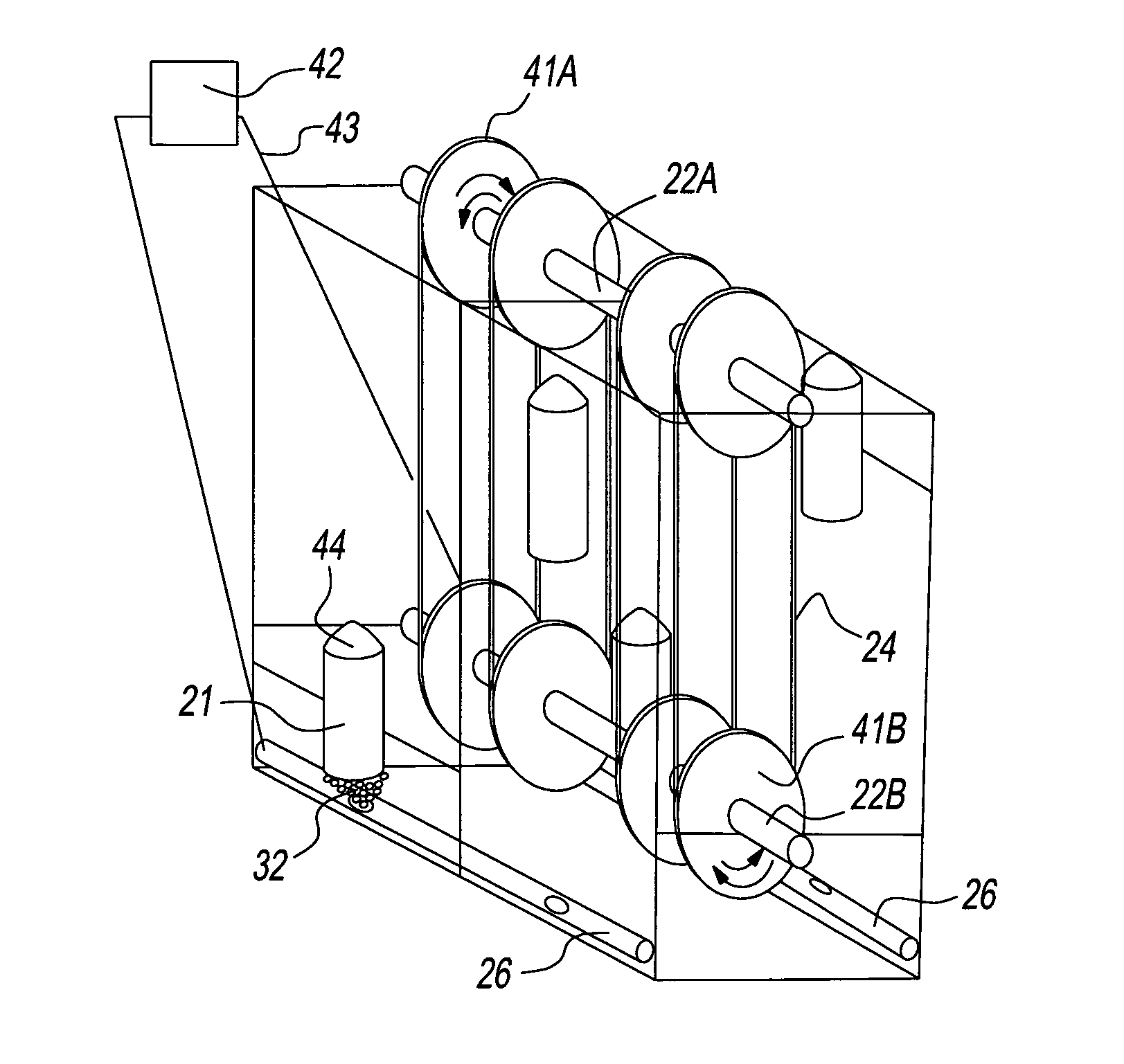
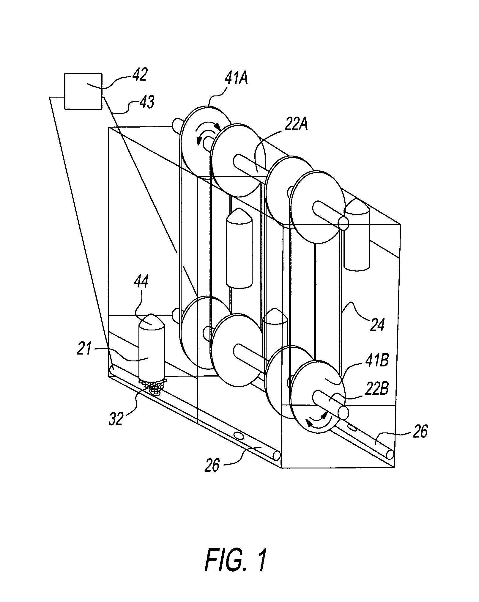
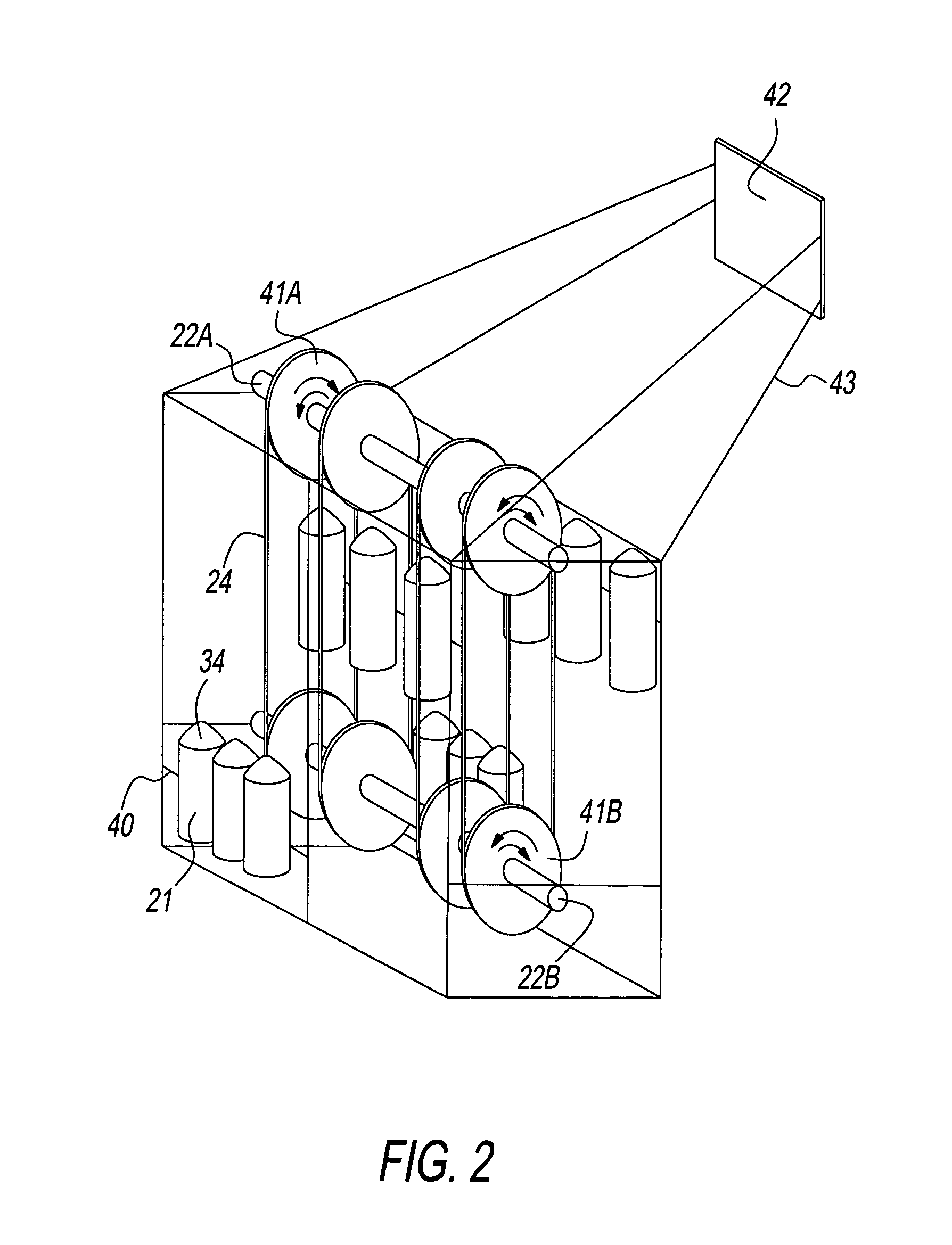
[0041]The vertical gravity / buoyancy power generator apparatus is presented in two embodiments though these should not be construed as limitations on the scope of the invention but, rather, the exemplification of several preferred embodiments thereof.

[0042]FIG. 1 shows the most basic, preferred embodiment for the vertical gravity / buoyancy power generator with two sets of containers (21) operating 90 degrees out of phase with the other set. A configuration for linking the sets is shown in FIG. 3A. An infinite number of container sets is possible with any variety of phasing. In operation the containers (21) ascend and descend through the liquid medium as they are attached by a chain / belt bracket (45) to or engage a chains or belt drives (24) which in turn rotate one way sprockets or pulleys (41A and 41B) which in turn rotate shaft(s) (22A and 22B).

[0043]At the bottom of its travel the closure means (44) seals the upper end of the container (21). A volume of gas (32) is introduced by th...


PUM


Abstract

A power generator utilizing gases and the gravitational force as efficiently as the buoyant force which act on an apparatus in a natural or man-made liquid medium and convert such forces into mechanical energy. The power generator includes methods for a plurality of weighted uniquely configured variable density containers which ascend and descend in a primarily vertical plane and which drive one or more chains, belts or conveyances with rotating sprockets or pulleys on horizontally aligned shafts in primarily a vertical arrangement upon such apparatus. The chains, belts or conveyances driven by the movement of the containers rotate the sprockets or pulleys (FIG. 1) and their associated shafts in both the ascending and descending motion creating mechanical power. Such power can be used to turn electrical generators or other mechanical machines which necessitate such power input.

Description

CROSS REFERENCE TO RELATED APPLICATIONS[0001]This application claims the benefit of Provisional Patent Application Ser. No. 61 / 269,749, filed Jun. 29, 2009 by the present inventorFEDERALLY SPONSORED RESEARCH[0002]noneSEQUENCE LISTING[0003]none[0004]Primary Class: 60 / 495; 60 / 496; 60 / 500BACKGROUND[0005]The vertical gravity / buoyancy power generator relates to the generation of power by harnessing the gravitational and buoyant forces which act on an apparatus in a liquid medium and converting such forces into mechanical energy. There exists a profound and continued interest around the world in the development of alternative energy from sources that are renewable and do not deplete resources or pollute the environment. Further, in the United States and many net oil importing countries, there is a need to develop and harness local energy resources to reduce dependence on foreign sources of energy, namely oil.[0006]As a consequence, alternative energy exploration and development proceeds a...

Claims


Application Information

Patent Timeline
Patent Type & Authority Patents(United States)
IPC IPC(8): F03B17/02F03G7/08
CPCF03B17/025F05B2210/401Y02E10/20
Inventor HASTINGS, DOUGLAS REYNOLDS
Owner HASTINGS DOUGLAS REYNOLDS
Learn More