
Microphone calibration with an RGSC beamformer

a beamformer and microphone technology, applied in the direction of ear treatment, sound producing devices, transmission, etc., can solve the problems of not being able to ensure a desired, ageing effects cannot be taken into account, etc., and achieve the effect of automatic calibration of the microphon

Inactive Publication Date: 2011-08-30
SIEMENS AUDIOLOGISCHE TECHN
View PDF6 Cites 11 Cited by
  • Summary
  • Abstract
  • Description
  • Claims
  • Application Information

AI Technical Summary

Benefits of technology

"The present invention is about a new RGSC beamformer that automatically compensates for component tolerances in the microphones used. This means that the beamformer can automatically adjust for any changes in the microphones over time, without the need for a separate calibration. The invention uses a method to calculate the transmission function of the filter or the corresponding filter coefficients to determine this transmission function. The technical effect of the invention is that it allows for accurate and efficient automatic calibration of the microphones during operation of the beamformer."

Problems solved by technology

Deviations in the signal transmission functions due to tolerances or ageing effects significantly impair the function of the beamformer, such that it may no longer be possible to ensure a desired interference noise suppression to an adequate degree with the microphone system used.
However this procedure has the disadvantage that ageing effects cannot be taken into account.

Method used


Image

  • Microphone calibration with an RGSC beamformer
  • Microphone calibration with an RGSC beamformer
  • Microphone calibration with an RGSC beamformer

Examples


Embodiment Construction

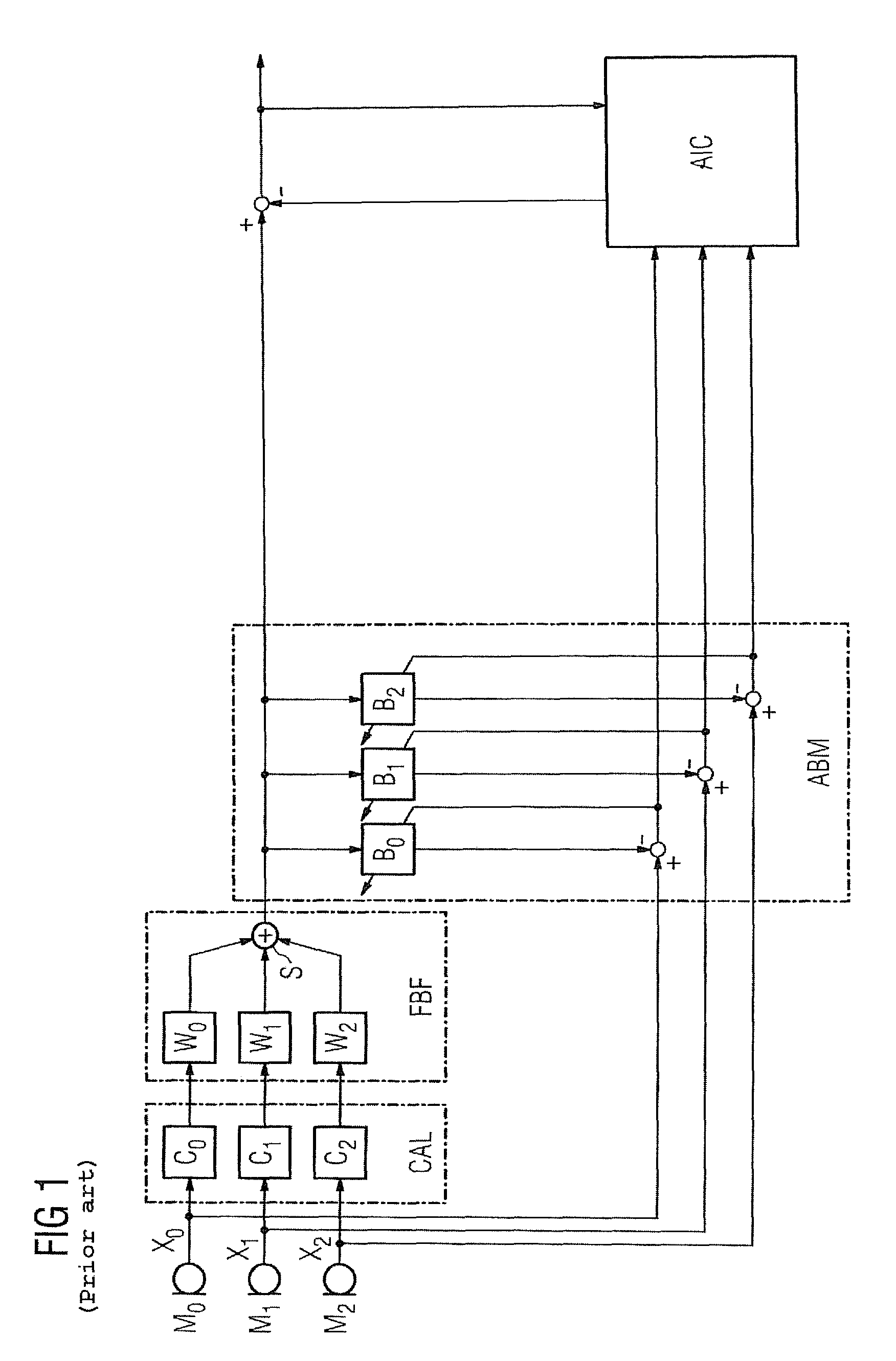
[0016]The RGSC beamformer known from the prior art cited in the introduction and shown in FIG. 1 is described briefly below with reference to an embodiment with three microphones:

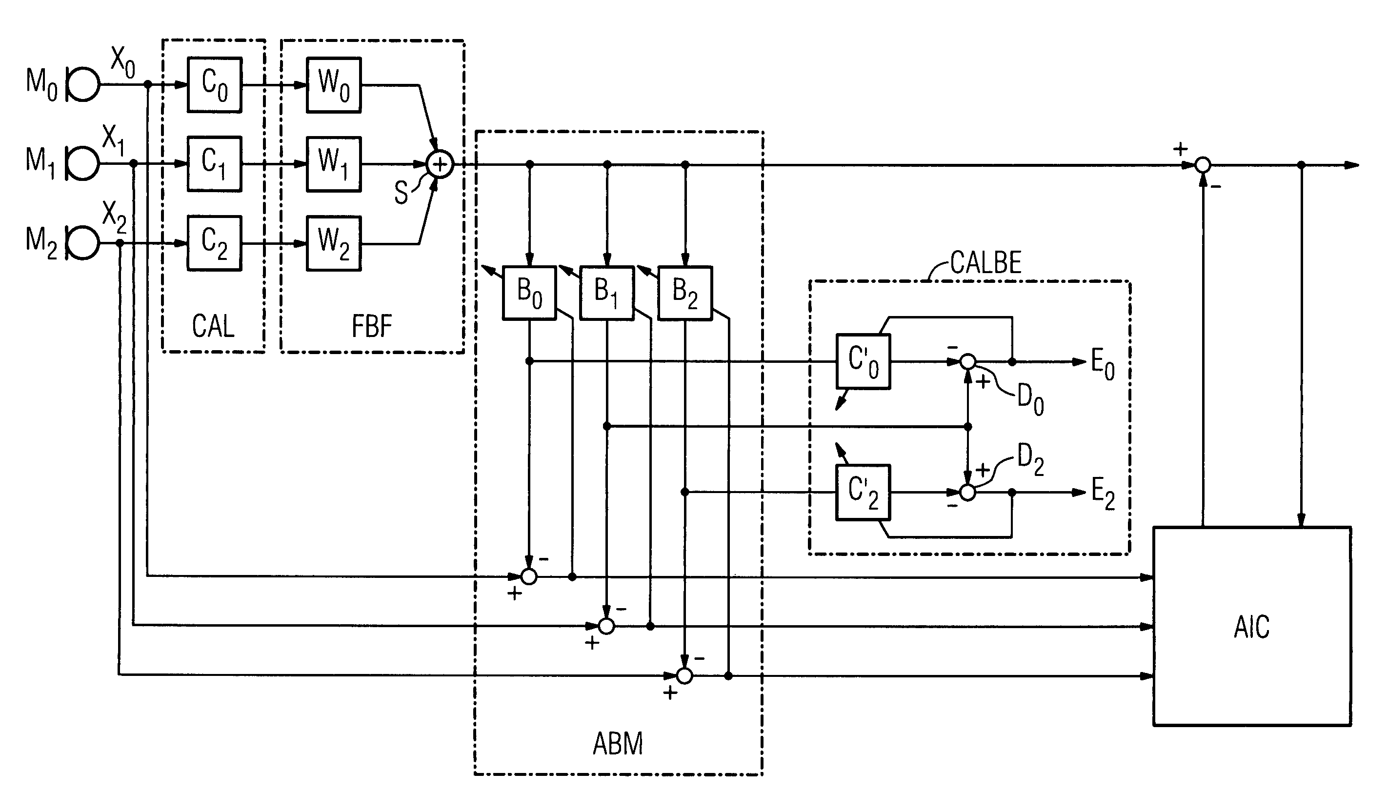
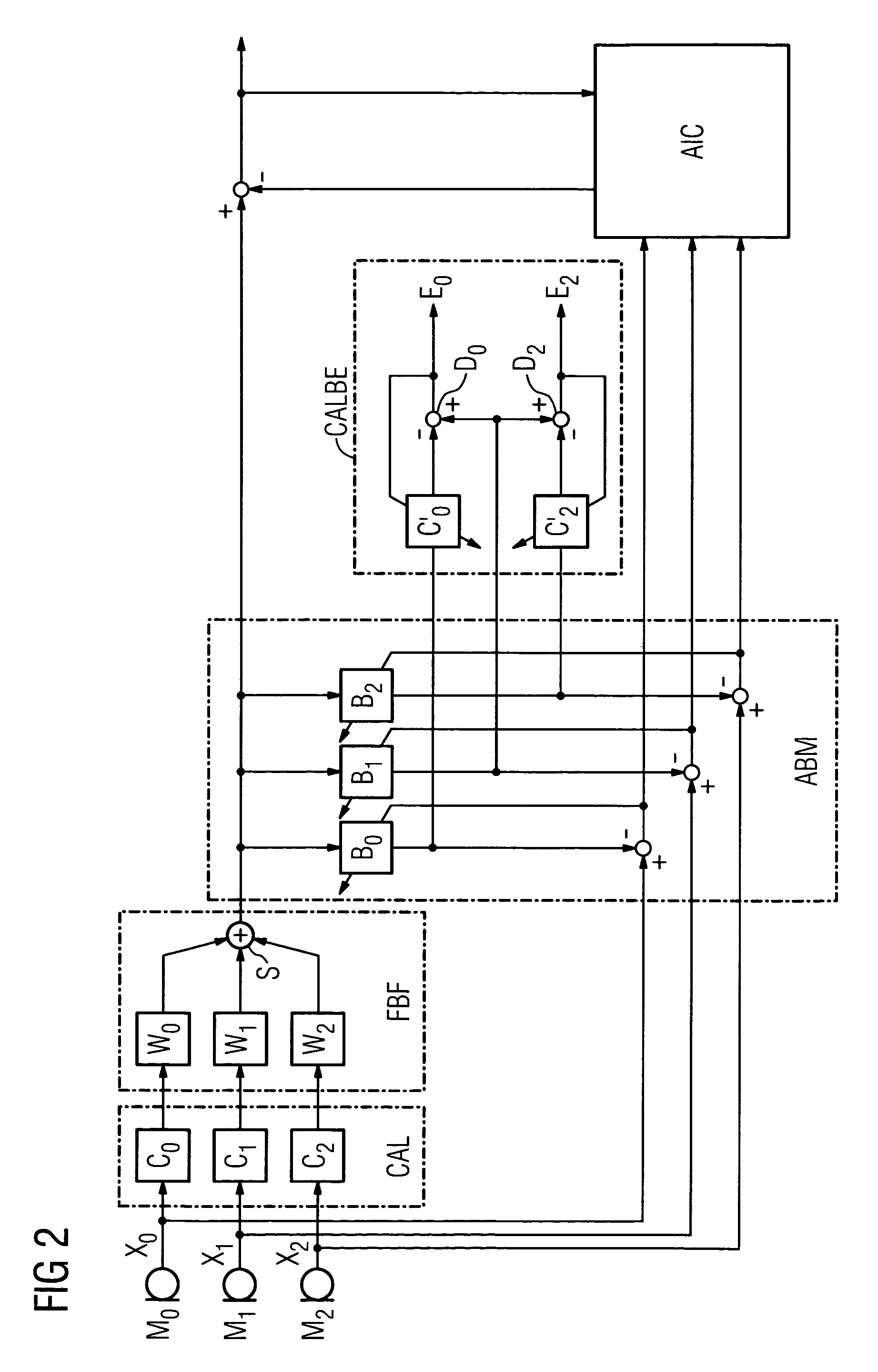
[0017]At least two microphones are required to set up an RGSC beamformer. However in theory any number of microphones can be used. In the exemplary embodiment the beamformer comprises the three microphones M0, M1 and M2. The calibration filters C0, C1 and C2 are connected downstream from the microphones to equalize component tolerances. Their transmission response is measured to equalize existing component tolerances of the microphones used. The filter coefficients of the calibration filters C0, C1 and C2 are then set such that the microphones combined with the downstream calibration filters show an at least approximately identical signal transmission response. The beamformer filters W0, W1 and W2 are connected downstream from the calibration filters in the signal paths of the microphones. The filtered micr...


PUM


Abstract

It is intended to improve and automate the calculation of calibration filters connected downstream from the microphones of an RGSC beamformer. To this end it is proposed that an adaptive calibration filter calculation unit be used, by means of which calibration filters are calculated from the output signals of adaptive blocking filters such that the power of an output signal of a blocking filter subtracted from a reference signal and filtered by means of a calibration filter respectively is minimized. The calibration filters connected downstream from the microphones are then replaced by the calibration filters thus determined.

Description

CROSS REFERENCE TO RELATED APPLICATIONS[0001]This application claims priority of German application No. 10 2005 047 047.5 filed Sep. 30, 2005, which is incorporated by reference herein in its entirety.FIELD OF THE INVENTION[0002]The invention relates to a circuit arrangement and a method for microphone calibration with an RGSC beamformer.BACKGROUND OF THE INVENTION[0003]An RGSC beamformer is known from Wolfgang Herbordt: “Combination of Robust Adaptive Beamforming with Acoustic Echo Cancellation for Acoustic Human / Machine Interface”, Dissertation, Friedrich-Alexander University Erlangen / Nuremberg, submitted 03.12.2003, page 99 ff.[0004]A system and method for picking up audio signals is known from US 2005 / 0047611 A1, with which a microphone array is used to reduce an interference signal compared to a useful signal. To this end the microphones of the microphone array are connected to a beamformer by way of a filter unit and a summation element. In the case of the mentioned document, ...

Claims


Application Information

Patent Timeline
Patent Type & Authority Patents(United States)
IPC IPC(8): H04R3/00
CPCH04R3/005H04R29/006H04R2430/25
Inventor KELLERMANN, WALTEROAK, PARIJAT ASHOK
Owner SIEMENS AUDIOLOGISCHE TECHN
Learn More