
Vehicle mirror and manufacturing method therefor

a technology for vehicle mirrors and manufacturing methods, applied in the field of vehicle mirrors, can solve the problems of increasing and the film with air bleed holes is unsuitable for vehicle mirrors, and achieve the effect of reducing the number of parts and assembly man-hours

Inactive Publication Date: 2011-08-23
MURAKAMI CORP
View PDF8 Cites 63 Cited by
  • Summary
  • Abstract
  • Description
  • Claims
  • Application Information

AI Technical Summary

Benefits of technology

The present invention relates to a vehicle mirror with a semitransparent reflective film and a dark-colored self-adhesive film that prevents light passing through the reflective film. The dark-colored self-adhesive film has air release channels that are eliminated when the film is attached to the mirror element, resulting in a more pleasant appearance. The use of the dark-colored self-adhesive film eliminates the need for a separate shatter-resistant film, reducing the number of parts and assembly man-hours. The manufacturing method involves preparing a mirror element with a reflective film, preparing a dark-colored self-adhesive film with air release channels, attaching the film to the rear face of the mirror element, and heating or pressurizing the mirror element to eliminate the air release channels.

Problems solved by technology

This increases the number of parts and number of assembly man-hours.
Alternatively, it is conceivable to form air bleed holes in the dark-colored self-adhesive film for air-bubble prevention, but a film with air bleed holes is unsuitable for a vehicle mirror because the air bleed holes are unpleasant to the eye, being visible from the front side of the mirror element.

Method used


Image

  • Vehicle mirror and manufacturing method therefor
  • Vehicle mirror and manufacturing method therefor
  • Vehicle mirror and manufacturing method therefor

Examples


first embodiment

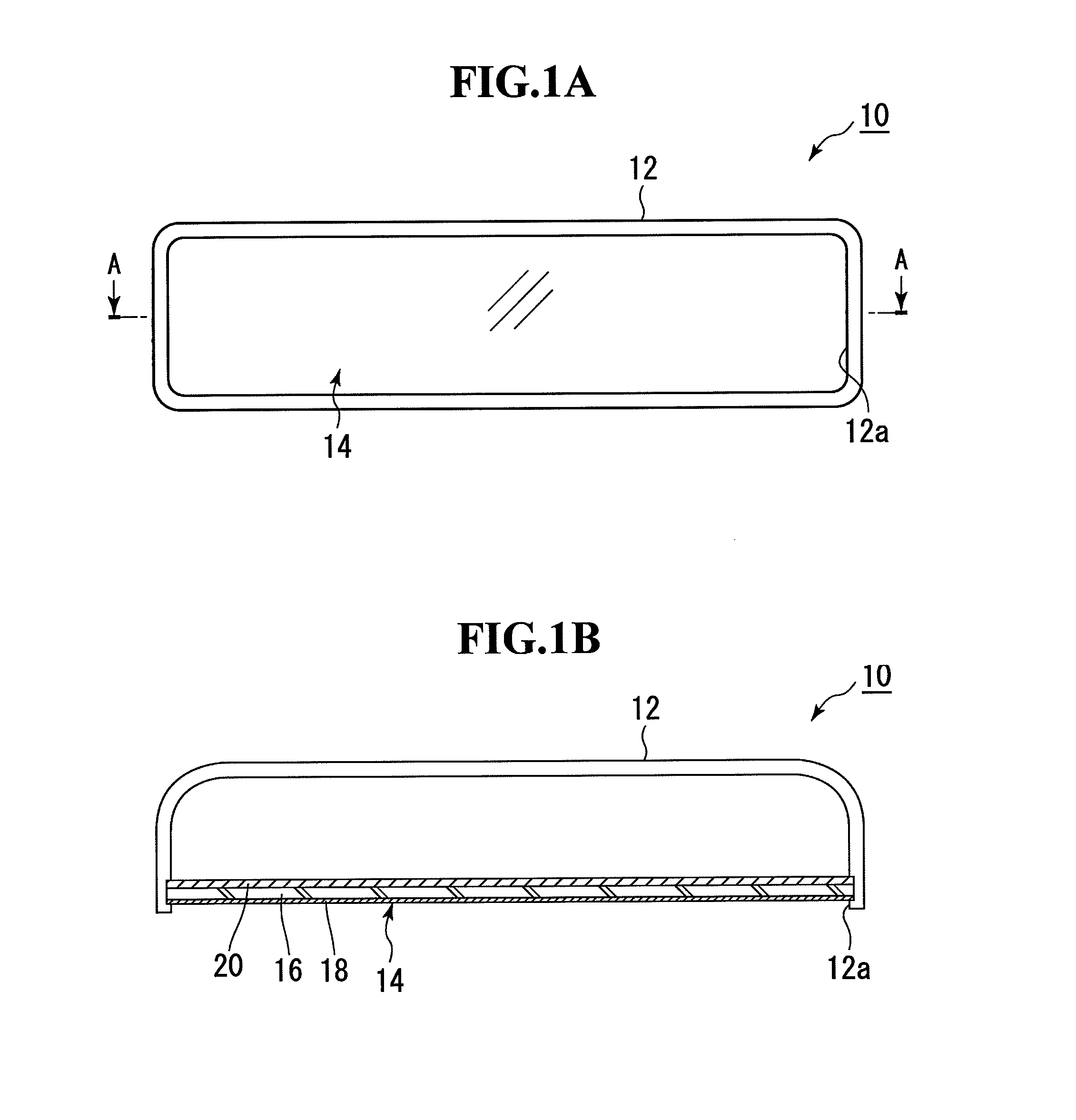
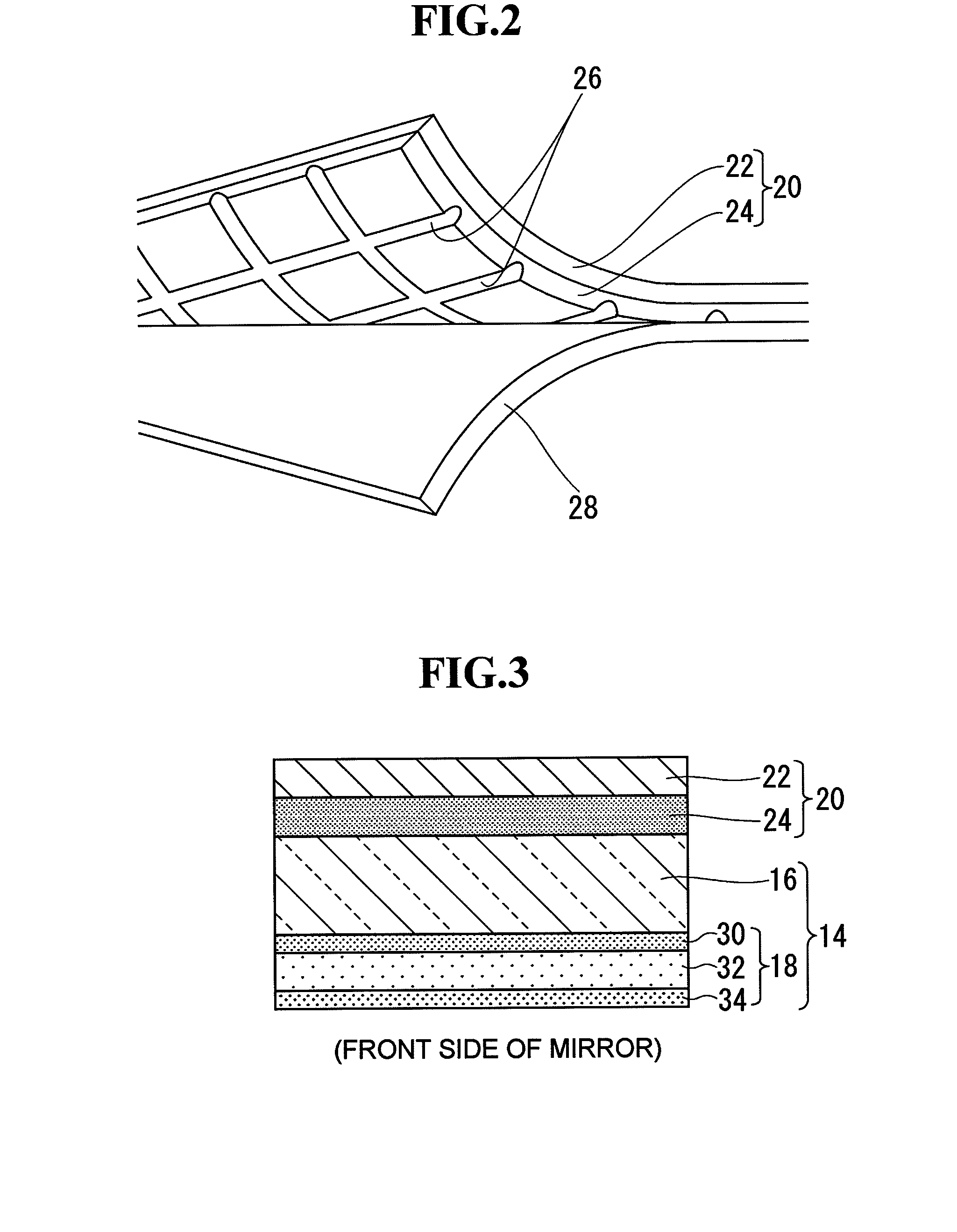
[0019]A vehicle mirror according to a first embodiment of the present invention is shown in FIGS. 1A and 1B. The vehicle mirror 10 is configured as a front surface anti-glare interior mirror. FIG. 1A is a front view and FIG. 1B is a sectional view taken along line A-A in FIG. 1A. Fitting a mirror element 14 in a front opening 12a of a housing 12 configures the interior mirror 10. The mirror element 14 is configured as a front surface mirror in which a semitransparent reflective film 18 made of a dielectric multilayer film is formed on the front face of a flat transparent substrate 16. Available materials for the transparent substrate include acrylic, polycarbonate, and other transparent resins as well as glass, but glass is suitable in terms of scratch resistance and formability (smoothness and low distortion). A dark-colored (e.g., black) self-adhesive film 20 is attached to the entire rear face of the mirror element 14. The dark-colored self-adhesive film 20 can be configured by f...

second embodiment

[0028]A vehicle mirror according to a second embodiment is shown in FIG. 6. The vehicle mirror is configured as a rear surface anti-glare interior mirror. Configuration of the second embodiment is the same as the first embodiment except for a mirror element 40, and thus illustration and description of overall configuration of an interior mirror will be omitted. The same components as those in the first embodiment are denoted by the same reference numerals as the corresponding components in the first embodiment. Structure of the mirror element 40 will be described. A semitransparent reflective film 18 is formed on the rear face of a transparent substrate 16 made of glass or the like. The semitransparent reflective film 18 is made of a dielectric multilayer film, which is formed of three layers—a high refractive index film 30, low refractive index film 32, and high refractive index film 34—laminated on the rear face of the transparent substrate 16 in this order. An anti-contamination ...

third embodiment

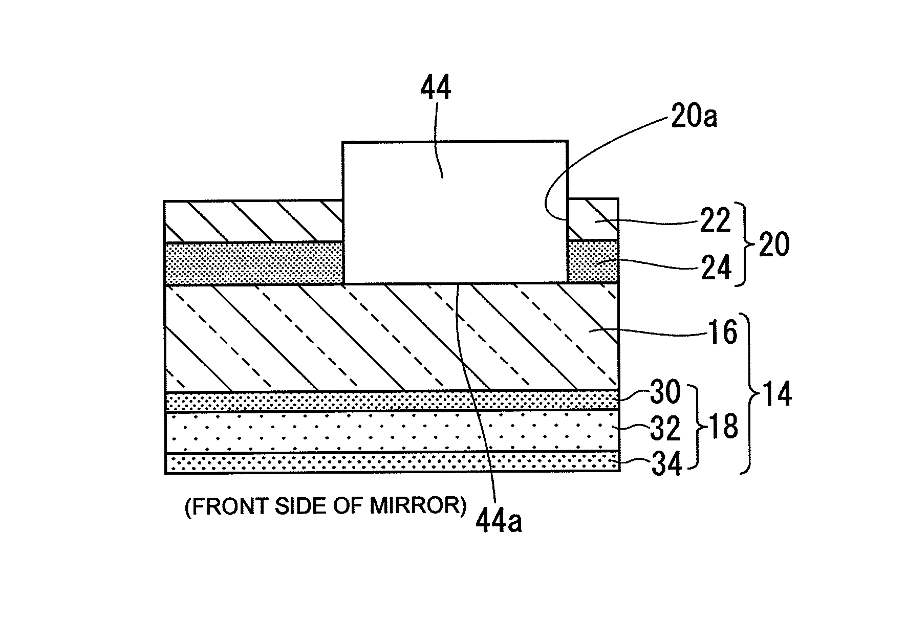
[0029]A vehicle mirror according to a third embodiment of the present invention is shown in FIGS. 7A and 7B. The vehicle mirror 42 is built by incorporating a light-emitting display 44 into the vehicle mirror 10 (a front surface anti-glare interior mirror) according to the first embodiment (FIG. 1). The same components as those in the first embodiment are denoted by the same reference numerals as the corresponding components in the first embodiment. An opening 20a is formed in an appropriate region (which is close to the driver's eye, i.e., the right corner on the surface of a mirror element 14 in FIGS. 7A and 7B) of a dark-colored self-adhesive film 20. In a housing 12, the light-emitting display 44 is installed behind the mirror element 14 with a display surface 44a facing the opening 20a of the dark-colored self-adhesive film 20. The light-emitting display 44 is a liquid crystal display, EL display, or the like. The light-emitting display 44 is mounted and supported at an appropr...


PUM

PropertyMeasurementUnit
thicknessaaaaaaaaaa
reflection peak wavelengthaaaaaaaaaa
reflectanceaaaaaaaaaa

Abstract

The present invention provides a vehicle mirror and a manufacturing method therefor which allow the rear face side of a mirror element to be dark-colored without using a color plate or color coating. A mirror element is configured by forming a semitransparent reflective film made of a dielectric multilayer film on the front face of a flat transparent substrate. A dark-colored self-adhesive film is attached to the rear face of the mirror element. The dark-colored self-adhesive film is configured by forming an adhesive layer on the rear face of a dark-colored film layer by means of application. Grid-like air release channels are formed at fine pitches with minimal depth on an entire surface of the adhesive layer. After the dark-colored self-adhesive film is attached to the rear face of the mirror element, the grid-like air release channels visible from a front side of the mirror element are eliminated by heating and / or pressurizing.

Description

[0001]The disclosure of Japanese Patent Application No. JP2009-42688 filed on Feb. 25, 2009 including the specification, drawings, claims and abstract is incorporated herein by reference in its entirety.BACKGROUND OF THE INVENTION[0002]1. Field of the Invention[0003]The present invention relates to a vehicle mirror equipped with a semitransparent reflective film and a manufacturing method for the vehicle mirror.[0004]2. Description of the Related Art[0005]Examples of vehicle mirrors equipped with a semitransparent reflective film are described in Japanese Utility Model Laid-Open No. 60-49045 and Japanese Patent Laid-Open Nos. 2000-255321, 2000-153736, and 2002-67806. In vehicle mirrors equipped with a semitransparent reflective film, the rear face side of a mirror element is made black or otherwise dark to block light passing through the semitransparent reflective film. For example, according to Japanese Utility Model Laid-Open No. 60-49045, a black absorbing film is formed on the r...

Claims


Application Information

Patent Timeline
Patent Type & Authority Patents(United States)
IPC IPC(8): G02B27/14G02B5/08G09G5/00B60R1/04B60R1/12
CPCB60R1/088G02B5/0833Y10S359/90
Inventor TAKAYANAGI, SHINYANAKAMURA, MASATOSHI
Owner MURAKAMI CORP
Learn More