Multi-sensor system for the detection and characterization of unexploded ordnance

a multi-sensor system and unexploded technology, applied in the field of unexploded ordnance detection and characterization, can solve the problems of mechanically difficult to position the receiver in a true null position, the receiver is limited in the electronic range, and the dynamic range problem, so as to reduce the sensitivity of the receiver element and reduce the deformation of the device

Active Publication Date: 2011-08-16
RGT UNIV OF CALIFORNIA
View PDF2 Cites 11 Cited by
  • Summary
  • Abstract
  • Description
  • Claims
  • Application Information

AI Technical Summary

Benefits of technology

[0024]This invention is directed to improvements to the UXO detection devices as described in our earlier provisional applications, the receiver and transmitter elements arranged in a novel configuration which greatly reduces the sensitivity of the receiver elements to mis-positioning. The arrangement of the transmitter coils also provides a more stable platform which reduces deformation of the device as it is rolled over the terrain to be interrogated. The principals of operation are similar to those applicable to the earlier systems, the principal difference being the use of three pairs of orthogonally disposed transmitting coils, and the placement of the symmetric receiving coil pair sets relative to the transmitting coils.

Problems solved by technology

The basic design challenge for these system is to provide a means to measure the secondary fields and relate them quantitatively to the location and parameters (size, shape and metal content) of the object (hereinafter called the target).
A design challenge for a practical system is to find a means to accurately measure the small secondary fields from the target in the presence of the much larger inducing field from the transmitters.
This is called the dynamic range problem.
Fundamentally any receiver is limited electronically in the range of voltage it can accommodate.
The practical problem is that it is mechanically difficult to position the receiver in a true null position.
The minutest deformation of the support structure by thermal expansion or vibration introduces large amounts of primary field and compromises the desired sensitivity of the receiver.
Unfortunately these transient systems are not completely immune from the dynamic range problem.
While in principle the receiver should only see the secondary fields in the off-time of the transmitter, the fact is that the physical device comprising the receiver, the coil and its amplifiers are still subject to the primary transient and thus experience huge voltages just before they are expected to function at full null signal sensitivity.
Experience has shown that even this system suffers from the problem of inexact null coupling due to mechanical deformation of the structure, both in the manufacturing step, and in the deployment of the unit in the field, where the coil supporting structures themselves may deform as the unit is moved over the terrain to be interrogated.
Further, the receiver coils are so close to the transmitter windings that significant leakage of the primary field onto the receiver circuit during the shut-off transient may occur and cause over range distortions of the recovered secondary transient wave form.

Method used


Image

  • Multi-sensor system for the detection and characterization of unexploded ordnance
  • Multi-sensor system for the detection and characterization of unexploded ordnance
  • Multi-sensor system for the detection and characterization of unexploded ordnance

Examples


Embodiment Construction

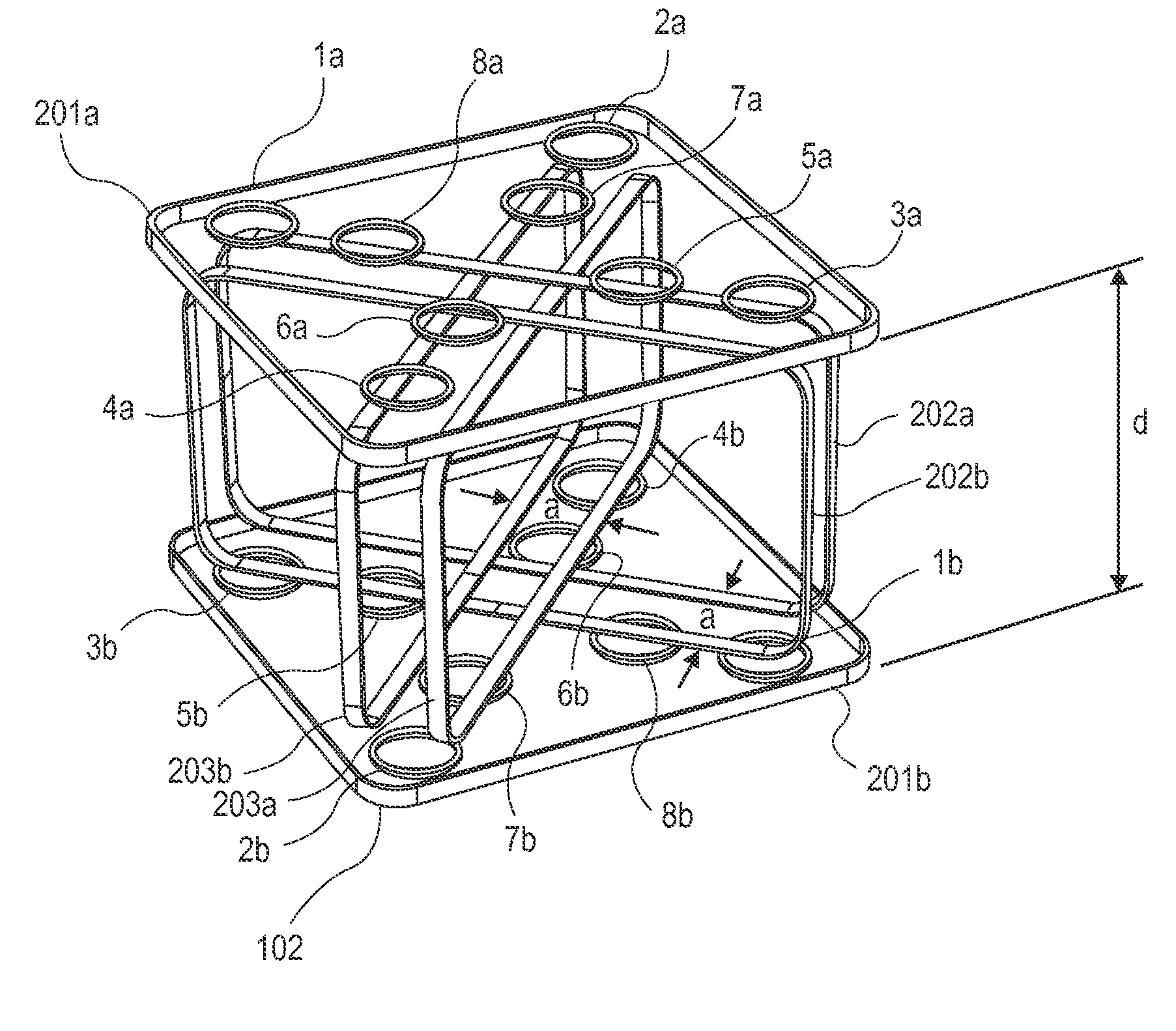
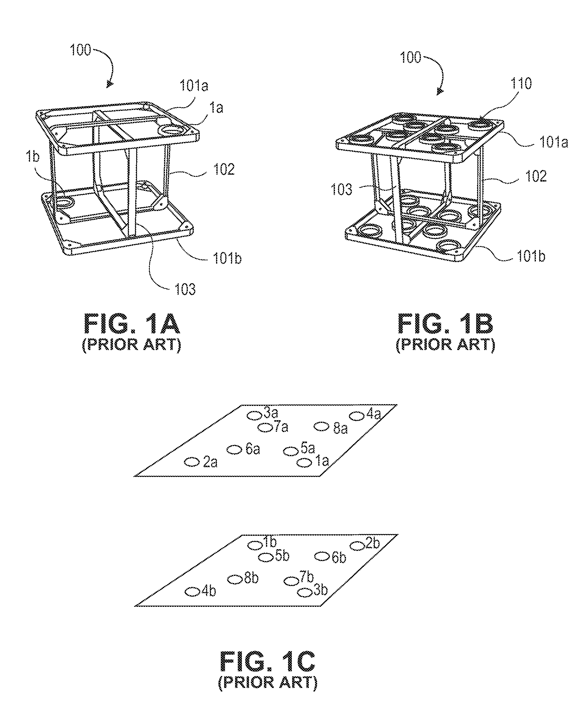
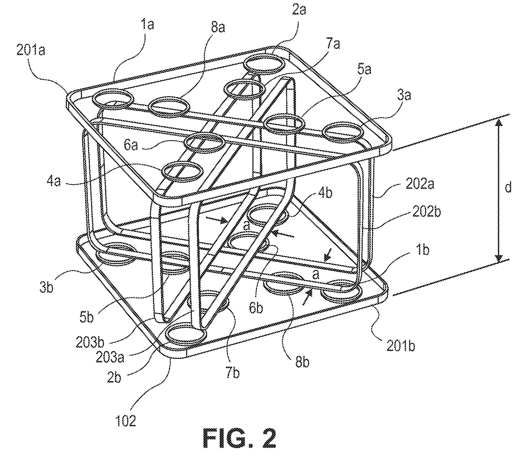
[0032]The new coil arrangement according to an embodiment of the invention is illustrated in FIG. 2, the two single vertical transmitter coils 102 and 103 of the prior art, FIG. 1, replaced by two pairs of coils (202a-202b, and 203a-203b), the individual coils of each pair separated by a distance “a”. The first receiver of each of the 8 receiver coil pairs (coils 1a-8a) is positioned directly over-top, that is laterally centered, relative to transmitter coil pairs 202 and 203. For ease of illustration, the frames which house the coil windings are shown, the frames in fact labeled 201a,b, 202a,b and 203a,b, the windings themselves nestled inside the frames, which frames provide the structural skeleton for the system. As with the coils described in our earlier provisional applications the frame itself may be formed from such non-conductive materials as wood, plastic, or aluminum.

[0033]FIG. 3A is a representational illustration in cross section of the flux field for one of the receiver...


PUM


Abstract

To fully characterize the inductive response of an isolated conductive object, such as buried unexploded ordinance, one needs to measure its response to stimulation by primary magnetic fields in three linearly independent (e.g., approximately orthogonal) directions. In one embodiment this is achieved by measuring the response to magnetic fields of three independent transmitters arranged to have magnetic fields that are linearly independent. According to the apparatus and methods employing the system of this invention, multiple transmitters and receivers of known relative position and orientation on a single platform are used. In a preferred embodiment, matched sets of receiver pairs connected in gradient mode are positioned adjacent to closely spaced pairs of transmitting coils, such that a minor displacement of one or both of the receiver coil pairs relative to the paired transmitting coils will not affect the detected secondary signals emitted by a buried metallic object.

Description

CROSS-REFERENCE TO RELATED APPLICATIONS[0001]This application claims priority to U.S. Provisional Patent Application 61 / 028,800, filed Feb. 14, 2008, which in turn claims priority to U.S. Provisional Patent Application 60 / 975,911, filed Sep. 28, 2007, which applications are hereby incorporated by reference in their entireties.STATEMENT OF GOVERNMENTAL SUPPORT[0002]The invention described and claimed herein was made in part utilizing funds supplied by the U.S. Department of Energy under Contract No. DE-AC03-76SF00098, and more recently tnder DE-AC02-05CH11231. The government has certain rights in this invention.BACKGROUND OF THE INVENTION[0003]1. Field of the Invention[0004]This invention relates generally to the detection of buried metallic objects, and more specifically to a novel apparatus to be used for the more accurate determination of the depth, size, and shape of buried metallic objects indicative of unexploded ordnance.[0005]In land areas where ordnance has been used, such a...

Claims


Application Information

Patent Timeline
Patent Type & Authority Patents(United States)
IPC IPC(8): G01V3/08
CPCG01V3/104
Inventor MORRISON, FRANK H.GASPERIKOVA, ERIKA
Owner RGT UNIV OF CALIFORNIA
Why Eureka
Try Eureka