Compound operation input device
a technology of input device and compound operation, which is applied in the field of compound operation input device, can solve the problems of poor achieve the effects of improving tactile touch in depressing operation, reducing device size, and increasing both height and thickness
- Summary
- Abstract
- Description
- Claims
- Application Information
AI Technical Summary
Benefits of technology
Problems solved by technology
Method used
Image
Examples
embodiment 1
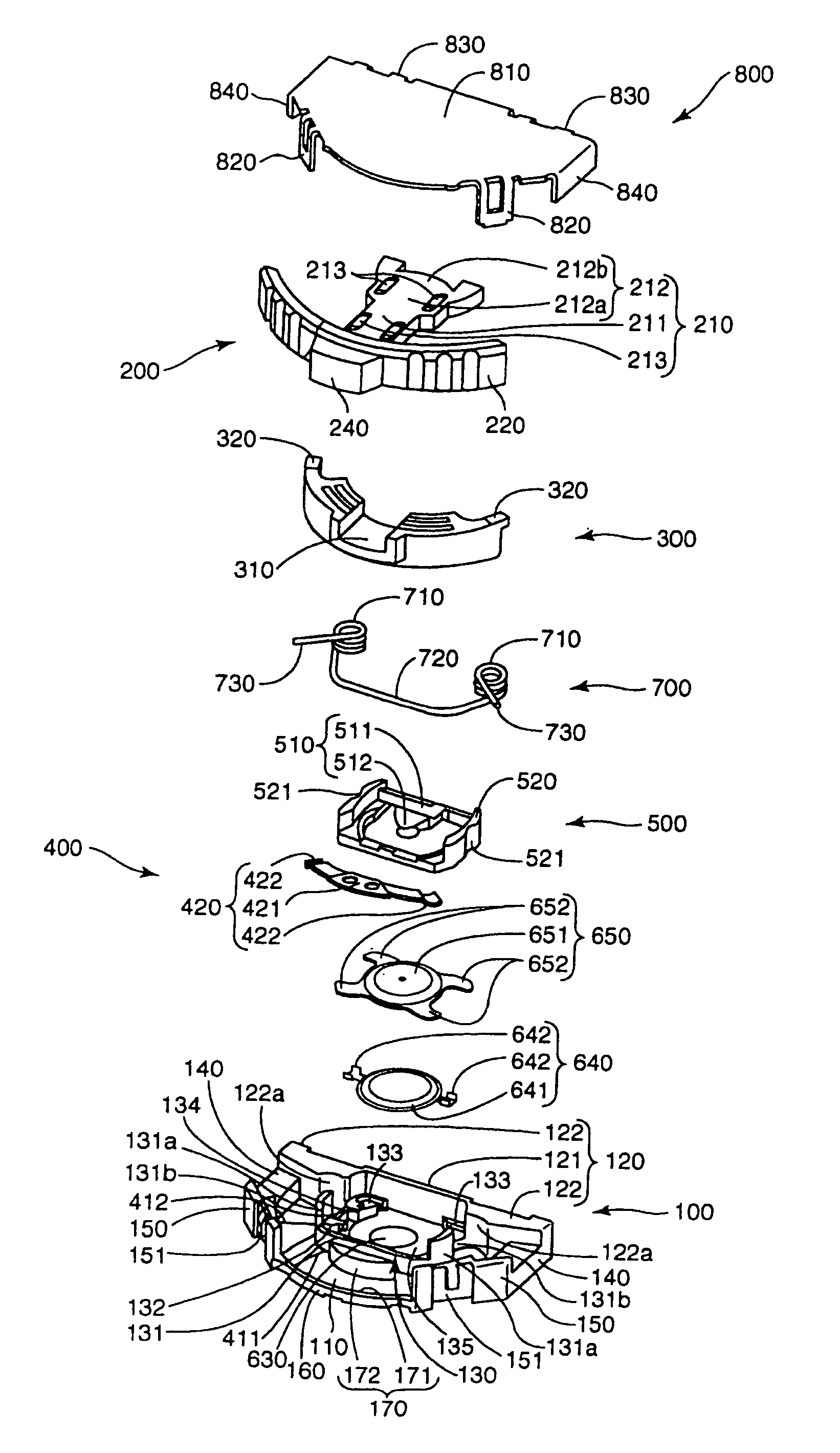
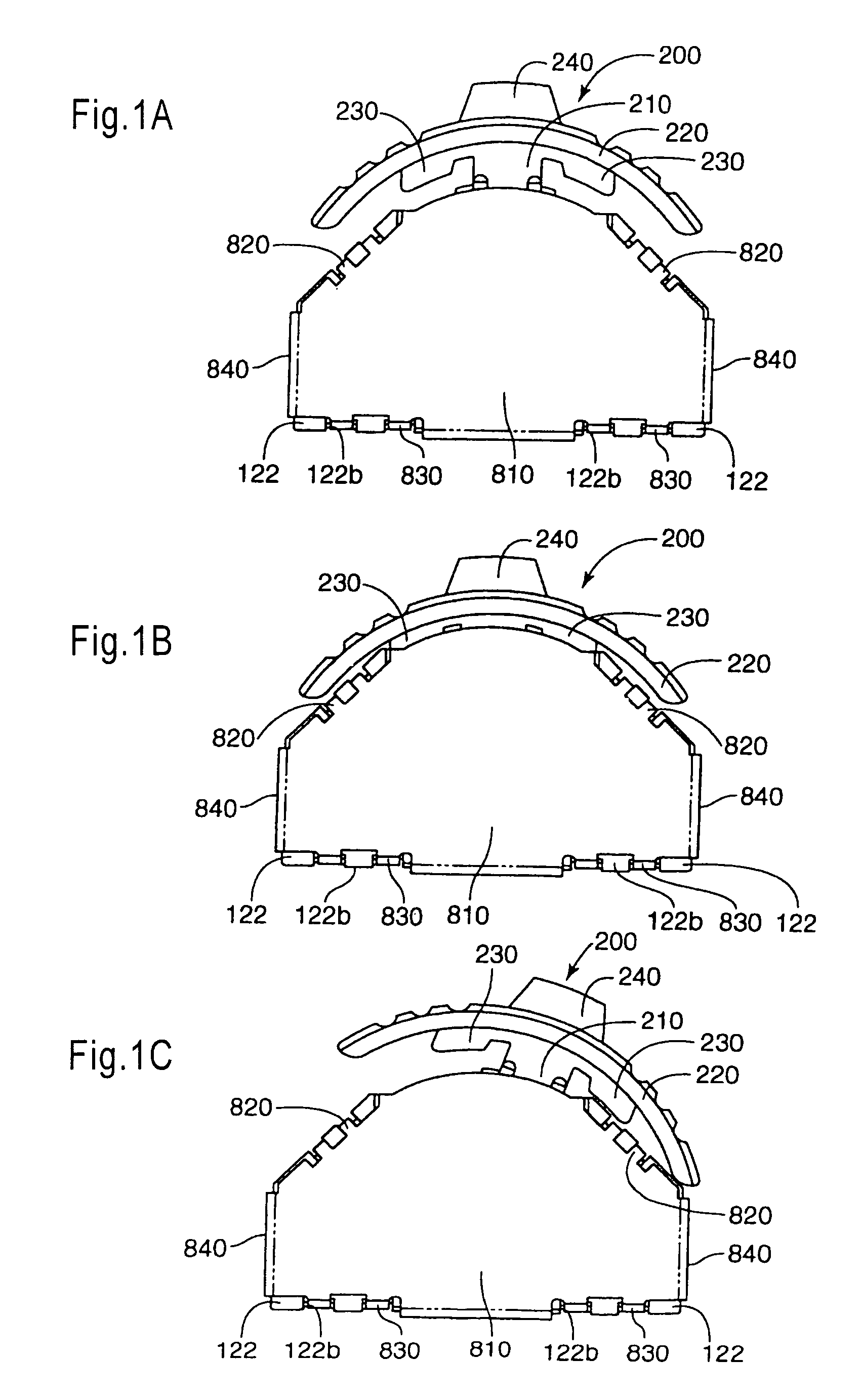
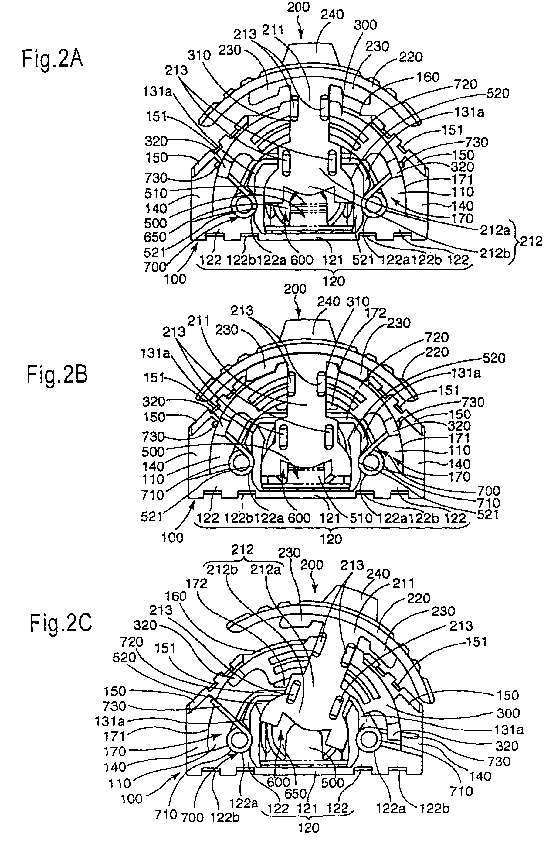
[0055]First, the compound operation input device according to a first embodiment of the present invention is explained with reference to the drawings. FIG. 1 is a schematic front view of the compound operation input device according to the first embodiment of the present invention. In FIG. 1, (a) is a diagram showing a state where an operating lever is located at the neutral position, (b) a diagram showing a state where the operating lever is depressed, (c) a diagram showing a state where the operating lever is in swing motion. FIG. 2 is a schematic front view showing the device a state where the frame ground of is removed. In FIG. 2, (a) is a diagram showing a state where the operating lever is located at the neutral position, (b) a diagram showing a state where the operating lever is depressed, and (c) a diagram showing a state where the operating lever is in swing motion. FIG. 3 is an exploded perspective view schematically showing the device, FIG. 4 a schematic diagram of a casi...
embodiment 2
[0149]Next, a compound operation input device according to a second embodiment of the present invention will be hereinafter explained with reference to the drawings. FIG. 7 is a diagram showing the compound operation input device according to the second embodiment of the present invention. In FIG. 7, (a) is a schematic front view, (b) a schematic rear view, (c) a schematic side view, and (d) a schematic bottom view. FIG. 8 is a schematic front view showing a state where the frame ground of the device removed, and FIG. 9 an exploded perspective view of the device. FIG. 10 is a schematic diagram of the casing showing the exposed parts of the fixed contact portion of the press switch and the contacts and the ground terminal of the position detector of the device. FIG. 11 is a sectional view of the device taken in line B-B in FIG. 7.
[0150]The compound operation input device according to this embodiment is different from the compound operation input device according to the first embodime...
embodiment 3
[0197]Hereinafter, the compound operation input device according to a third embodiment of the present invention is explained with reference to the drawings. FIG. 12 is an exploded perspective view showing the compound operation input device according to the third embodiment of the present invention, FIG. 13 a diagram of a casing showing a fixed contact portion of a press switch, contacts of a position detector and ground terminal of the device. In FIG. 13, (a) is a front view, (b) a sectional view taken in line C-C, and (c) a partly enlarged view in (b). FIG. 14 is a diagram showing an operating lever for the device. In FIG. 14, (a) is a front view, (b) a rear view, (c) a side view, (d) a plan view, (e) a bottom view, and (f) a sectional view taken in line D-D. FIG. 15 is a diagram showing a rotor of the device. In FIG. 15, (a) is a front view, (b) a rear view, (c) a side view, (d) a plan view, and (e) a bottom view. FIG. 16 is a diagram showing a pressing member of the device. In F...
PUM
 Abstract
Description
Claims
Application Information
 - R&D
- Intellectual Property
- Life Sciences
- Materials
- Tech Scout
- Unparalleled Data Quality
- Higher Quality Content
- 60% Fewer Hallucinations
Browse by: Latest US Patents, China's latest patents, Technical Efficacy Thesaurus, Application Domain, Technology Topic, Popular Technical Reports.
© 2025 PatSnap. All rights reserved.Legal|Privacy policy|Modern Slavery Act Transparency Statement|Sitemap|About US| Contact US: help@patsnap.com


