
Microfluidic autoregulator devices and arrays for operation with newtonian fluids

a microfluidic and autoregulator technology, applied in the field of microfluidic devices with nonlinear responses, can solve the problem and achieve the effect of expanding the potential complexity of the microfluidic architectur

Inactive Publication Date: 2011-08-09
CALIFORNIA INST OF TECH
View PDF4 Cites 0 Cited by
  • Summary
  • Abstract
  • Description
  • Claims
  • Application Information

AI Technical Summary

Benefits of technology

This solution expands the potential complexity of microfluidic architectures, enabling autoregulation, tunable current sources, microfluidic diodes, and rectifiers in Newtonian fluids, enhancing the capabilities of PDMS microfluidics and addressing limitations of existing two-dimensional devices.

Problems solved by technology

The resulting three dimensional connectivity greatly expands the potential complexity of microfluidic architecture.

Method used


Image

  • Microfluidic autoregulator devices and arrays for operation with newtonian fluids
  • Microfluidic autoregulator devices and arrays for operation with newtonian fluids
  • Microfluidic autoregulator devices and arrays for operation with newtonian fluids

Examples


Embodiment Construction

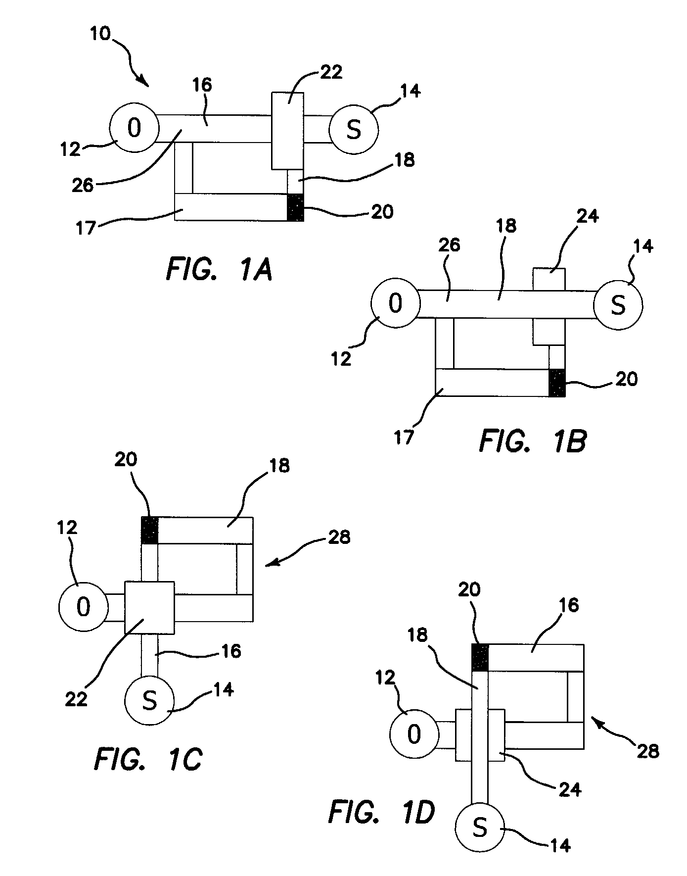
[0038]The future will witness many important advances in patterning, as made possible by the microfluidic via technology presented in the incorporated patent application referenced above. In the multilayer world of microfluidic valves, vias remove the distinction between control and flow channels, because the same three dimensional channel can now be a control channel in one section of the chip and a flow channel in another. Therefore, the same three dimensional channel can act as a control channel upon itself. This feature forms the basis of autoregulatory devices, which are disclosed below. Previous work in microfluidic autoregulation utilized the non-Newtonian rheological properties of concentrated polymeric solutions. By contrast, the invention is the first to show microfluidic autoregulation in Newtonian fluids and thus in environments typical to most microfluidic applications.

[0039]While fluidic devices of similarly nonlinearity have been reported in the prior art, those devic...


PUM


Abstract

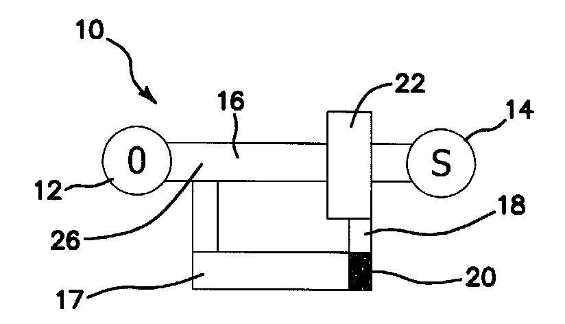
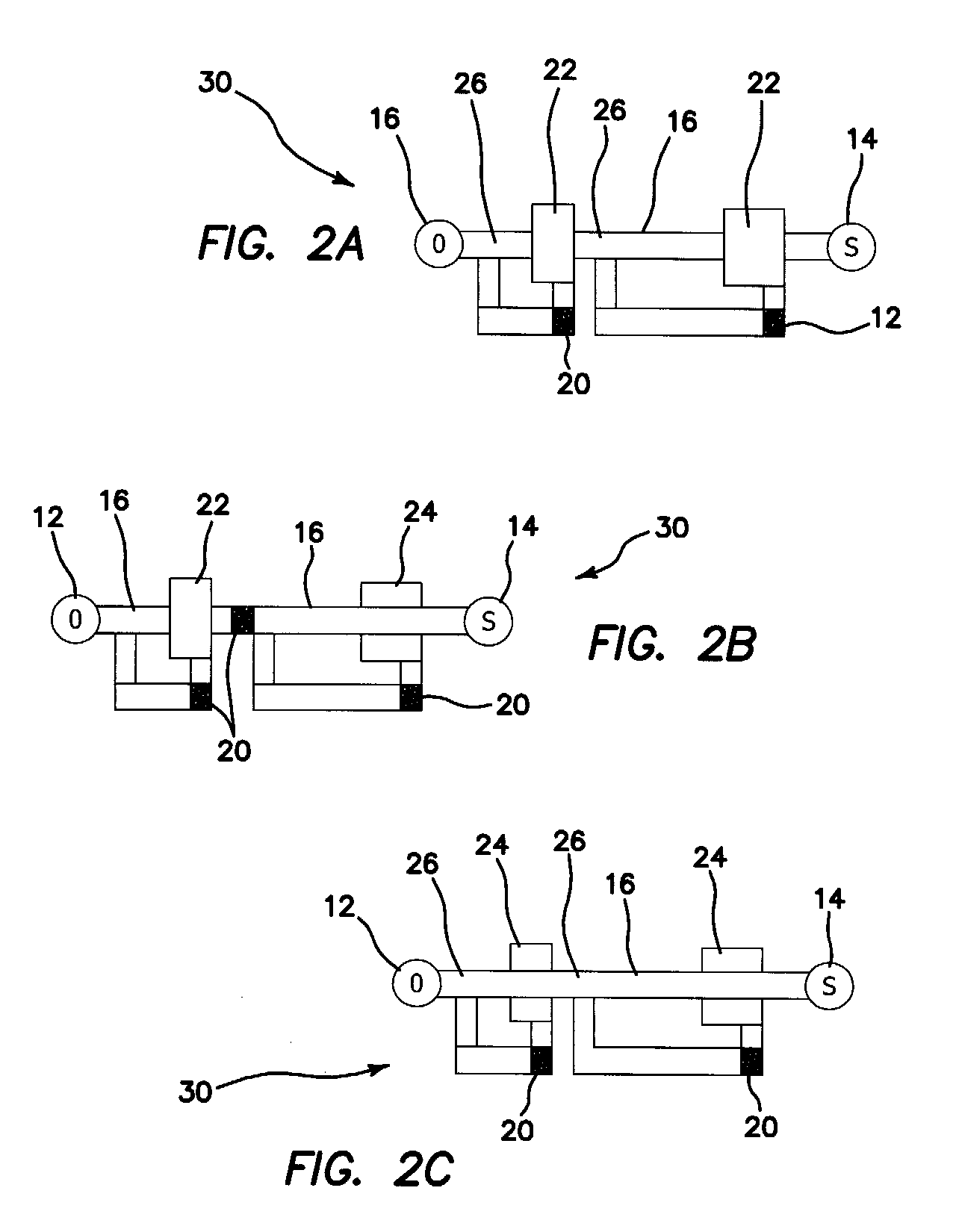
By use of the vias a microfluidic autoregulator is fabricated comprising an origin of a fluid, a sink for the fluid, a main flow channel coupling the origin and the sink, a valve communicated to the main flow channel to selectively control flow of fluid therethrough, and means dependent on flow through the main flow channel for creating a pressure differential across the valve to at least partially activate the valve to control flow of fluid through the main flow channel. The means for dependent on flow for creating a pressure differential comprises either a dead-end detour channel from the flow channel to the valve, or a loop channel fed back to the control chamber of the valve.

Description

RELATED APPLICATIONS[0001]The present application is related to U.S. Provisional Patent Application Ser. No. 60 / 740,988, filed on Nov. 30, 2005 and Ser. No. 60 / 764,245, filed on Feb. 1, 2006, each of which are incorporated herein by reference and to which priority is claimed pursuant to 35 USC 119.[0002]The U.S. Government has certain rights in this invention pursuant to Grant No. 1R01 HG002644-01A1 awarded by the National Institutes of Health.BACKGROUND OF THE INVENTION[0003]1. Field of the Invention[0004]The invention relates to the field of microfluidic devices with nonlinear responses.[0005]2. Description of the Prior Art[0006]Microfluidics is a technology that is establishing itself as an innovative practical tool in biological and biomedical research. Microfluidics offers the advantages of economy of reagents, small sample handling, portability, and speed. PDMS (polydimethylsiloxane) microfluidics in particular also offers industrial up-scalability, parallel fabrication, and a...

Claims


Application Information

Patent Timeline
Patent Type & Authority Patents(United States)
IPC IPC(8): F16K31/36
CPCF16K99/0001F16K99/0015F16K99/0026F16K99/0057G05D7/0694B01L3/5027F16K2099/008F16K2099/0084Y10T137/218Y10T137/2202Y10T137/7796
Inventor KARTALOV, EMILSCHERER, AXELANDERSON, W. FRENCHWALKER, CHRISTOPHER I.
Owner CALIFORNIA INST OF TECH
Learn More