Pipe cutting apparatus and method of using the same

a cutting device and pipe technology, applied in the direction of portable lathes, tube shearing machines, auxillary welding devices, etc., can solve the problems of inconvenient use, inconvenient use, and inability to precisely measure the length of pipes needed for a particular installation,

Active Publication Date: 2011-08-09
MARPLE MELVYN JAMES +1
View PDF35 Cites 21 Cited by
  • Summary
  • Abstract
  • Description
  • Claims
  • Application Information

AI Technical Summary

Benefits of technology

[0017]It is an advantage of the present invention that a reference position may be defined on the apparatus so that an initial cut location may be registered with respect to the reference position to provide the desired orientation of the cut with respect to the pipe. This is particularly advantageous when forming cuts on opposite ends of a pipe and require a defined orientation of one cut with respect to the other (for example, a first end cut may be rotated 30° with respect to a second, opposing end cut so as to fit between other associated pipe sections).
[0018]Further, the use of the processor-based cutting arrangement allows for various cut profiles to be “saved”, so that if a number of cuts of the same profile need to be performed time and again, there is no need to re-enter the input data associated with the specific pipe parameters or re-calculate the movements of the cutting head.
[0019]In another embodiment of the present invention, a multiple number of axes (beyond translational and rotational) may be incorporated into the processor-controlled cutting operation to allow for pipes having non-cylindrical geometries (e.g., square, rectangular, oval, hexagonal, etc.) to be cut and / or for a sequential number of through-holes / inscriptions to be made along a length of pipe without resetting the pipe in the tool.

Problems solved by technology

Additionally, the tool bit requires rigid, yet movable, holding supports.
In the past, the lack of portable pipe cutting equipment required that all pipes be precut before transporting to an installation location.
In many instances, however, the precise lengths of pipe needed for a particular installation are not known until the pipe is being installed on a section-by-section basis.
All of the above necessities naturally resulted in cumbersome and costly procedures and equipment.
While an improvement over the prior art in terms of providing a portable cutting tool, the arrangement of Brown remains relatively inefficient and unable to perform complex cuts.
Again, however, the ability to create compound cuts (e.g., beveled edges and the like) is limited.
This is considered to be a tedious process since each pipe needs a separate profile and, in addition, the profile must be applied to the surface of the pipe with due care.
Various other hand tools may be used to form complicated pipe cuts, but are often considered to be too slow, inaccurate and / or inefficient to utilize in any installation or production facility that requires multiple complex cuts to be performed.

Method used


Image

  • Pipe cutting apparatus and method of using the same
  • Pipe cutting apparatus and method of using the same
  • Pipe cutting apparatus and method of using the same

Examples


Embodiment Construction

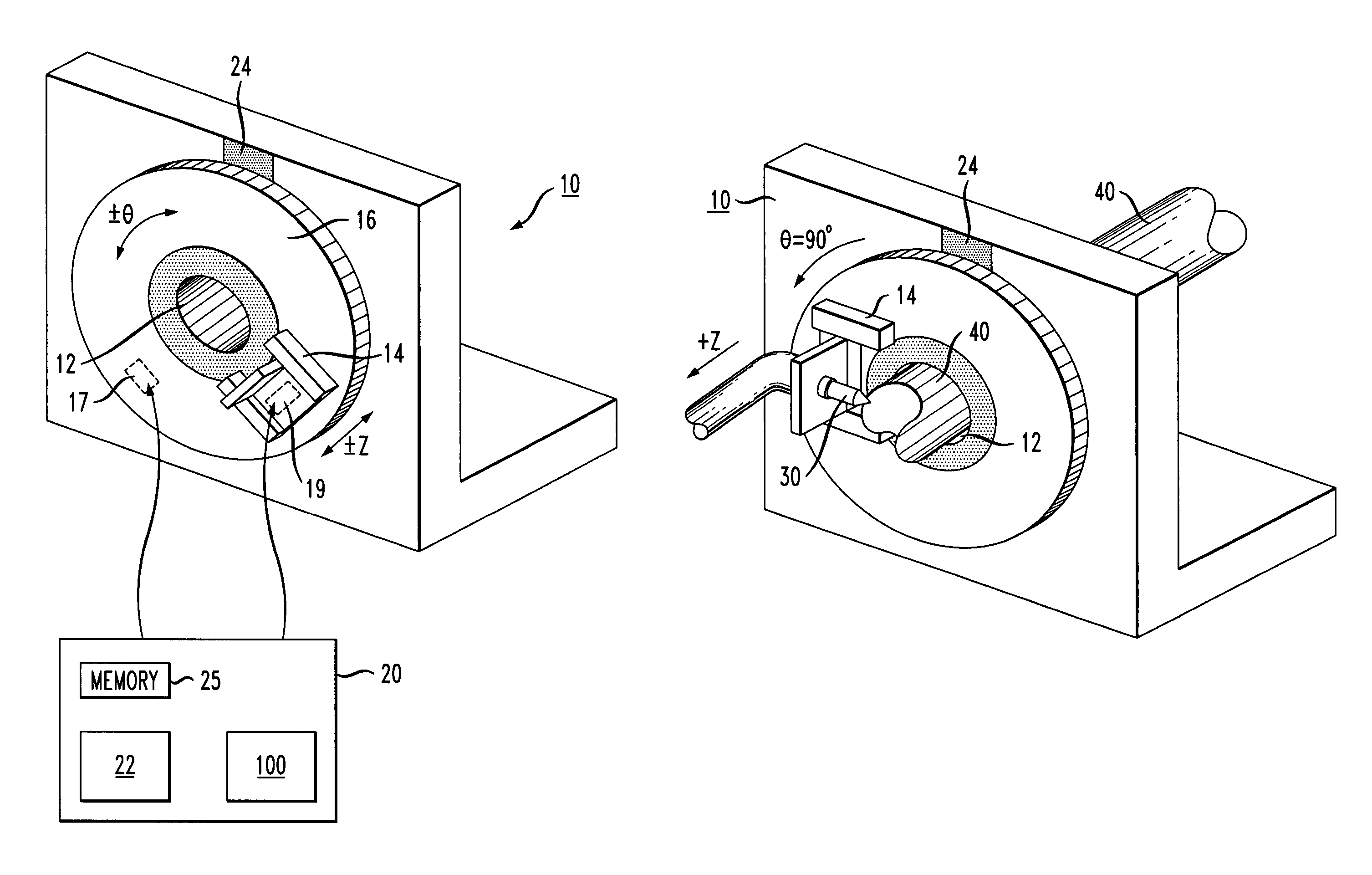
[0024]In accordance with the present invention, the inventive cutting arrangement comprises a processor-controlled cutting apparatus 10, as shown in FIG. 1. Referring to FIG. 1, apparatus 10 includes a central aperture 12 that is used to fixedly hold a pipe (not shown) in place while the cut is being made. While the description of the present invention refers to cutting a “pipe”, it is to be understood that this term also refers to a tube, rod or any other element (of any material) in which a cut, through-hole or inscription is desired to be made. As further discussed below, while the particular embodiment of the present invention as shown in FIG. 1 is well-suited for cutting a cylindrical pipe, the apparatus of the present invention may utilize information about multiple axes (beyond translational and rotational) to perform cuts within and along “pipes” of various non-cylindrical geometries.

[0025]Referring back to FIG. 1, cutting apparatus 10 further comprises a cutting head 14 tha...


PUM

PropertyMeasurementUnit
constant angleaaaaaaaaaa
angleaaaaaaaaaa
thicknessaaaaaaaaaa

Abstract

An apparatus for cutting a pipe includes a housing with a central aperture for holding the pipe in a fixed position. A rotatable collar is mounted on the outer surface of the fixed housing, with a cutting head attached to the collar. The cutting head is configured to translate forward and backward such that the combination of the rotational movement of the collar and the translational movement of the cutting head is capable of performing complex cuts without ever moving the pipe. A number of different cutting tools (laser, plasma, etc.) may be attached to the cutting head, and a variety of different tasks may be performed including cutting completely through the entire pipe, inscribing on the pipe surface, forming through-holes along the pipe, and the like.

Description

CROSS-REFERENCE TO RELATED APPLICATION[0001]This application claims the benefit of Provisional Application No. 60 / 819,845, filed Jul. 11, 2006.TECHNICAL FIELD[0002]The present invention related to pipe cutting apparatus and, more particularly, to a cutting apparatus which holds the pipe in a fixed manner such that a cutting head moves radially and laterally about the pipe, the head being processor-controlled to perform any desired complex / compound cut, through-hole and / or inscription on the surface thereof.BACKGROUND OF THE INVENTION[0003]Generally, when it is desired to cut a pipe, it is mounted in and gripped by a chuck of a lathe and rotated while a non-rotating cutting tool is moved laterally into the rotating pipe. The cutting is accomplished in several successive turns of the pipe as the tool bit is moved gradually into the rotating pipe. The lathe requires a heavy bed which is fixed and contained in a permanent location, such as a machine shop. Additionally, the tool bit requ...

Claims


Application Information

Patent Timeline
Patent Type & Authority Patents(United States)
IPC IPC(8): B23B3/22
CPCB23D21/02B23K10/00B23K26/103B23K26/28B23K37/0533B24C1/045B26D3/162Y10T82/22B26F3/004Y10T82/2522B23K2201/06B23K2101/06Y10T83/0596B23B3/22B23B5/12B23B5/16B23D21/00
Inventor MARPLE, MELVYN JAMESMARPLE, JAMES ARTHUR
Owner MARPLE MELVYN JAMES
Why Eureka
Try Eureka