
X-ray CT system for x-ray phase contrast and/or x-ray dark field imaging

a phase contrast and x-ray technology, applied in the field of computed tomography, can solve the problems of difficult phase and amplitude determination of phase and amplitude of this intensity curve, significant quantity of expensive gold in addition to production cost, and difficult to realize the grating structure g/sub>2 with the absorber structure, etc., to achieve the effect of reducing technical requirements

Active Publication Date: 2011-07-19
SIEMENS HEALTHCARE GMBH +1
View PDF9 Cites 62 Cited by
  • Summary
  • Abstract
  • Description
  • Claims
  • Application Information

AI Technical Summary

Benefits of technology

[0014]An object of the present invention is to provide an x-ray CT system for x-ray phase contrast and / or x-ray dark field imaging of a scanned examination subject with at least one grating interferometer arranged on a gantry, that poses lower technical requirements for the grating structures that are used within the scope of the Talbot conditions and that is suitable for practical operation for the examination of objects of the size of human patients. This object is achieved by a CT system based on the following insights.

Problems solved by technology

Particularly the technical realization of the grating structure G2 with absorber structures has proven to be problematic since the smallest grating period p2 and the grating lines must have a high absorption.
At the same time, the area of G2 is the largest of all three gratings, which also requires a significant quantity of expensive gold in addition to the production cost.
In this embodiment of the disclosed CT system, however, a value-based analysis of the spatial intensity curve is not implemented per detector element, and thus the phase and amplitude of this intensity curve are also not determined analytically.
Furthermore, in published Patent Application WO 2007 / 12533 A1, a CT system for value-based determination of phase shifts with a Talbot interferometer is proposed in which the grating periods increase in the beam direction, wherein the examination subject can be placed between the second grating structure and third grating structure; however, the ratios of the grating periods relative to one another and the ratios of the intervals between the gratings that are proposed there are unsuitable in practice with a CT system.

Method used


Image

  • X-ray CT system for x-ray phase contrast and/or x-ray dark field imaging
  • X-ray CT system for x-ray phase contrast and/or x-ray dark field imaging
  • X-ray CT system for x-ray phase contrast and/or x-ray dark field imaging

Examples


Embodiment Construction

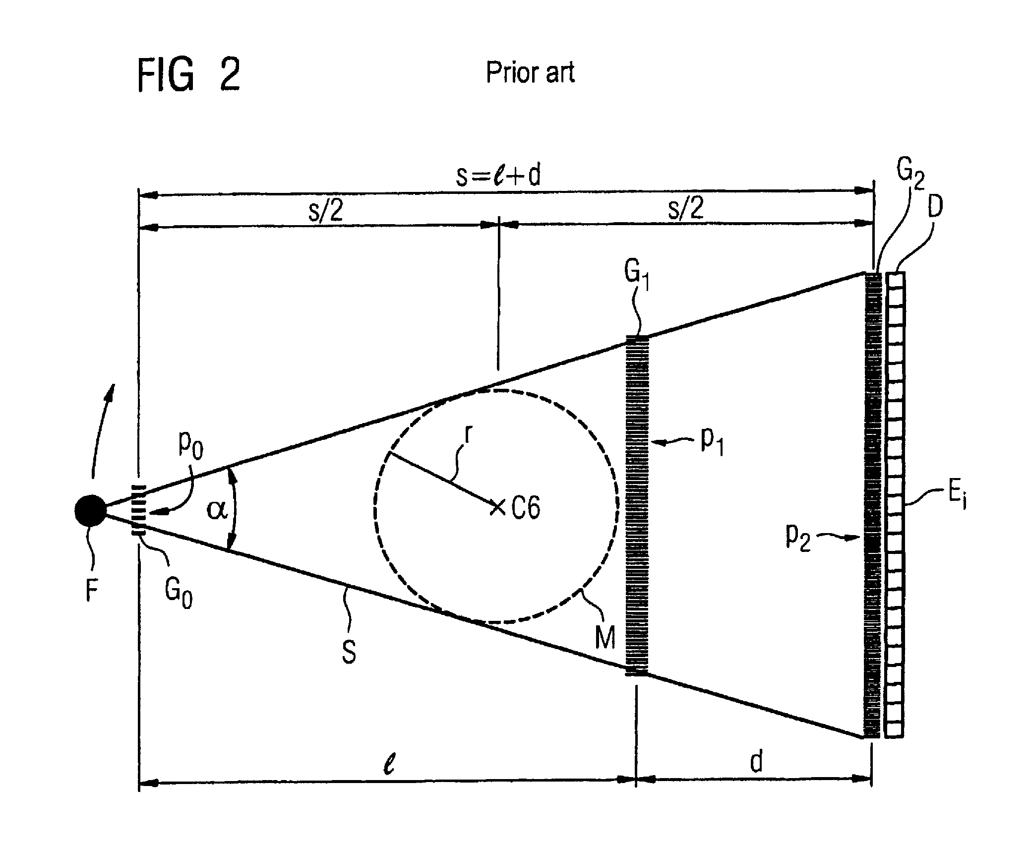
[0055]In the following the invention is described in detail with the aid of Figures, wherein only the features necessary for understanding the invention are shown. The following reference characters, variables and abbreviated designations are used: C1: x-ray CT system; C2: gantry housing; C3: gantry opening; C4: displaceable patient bed; C5: patient; C6: system axis; C7: control and computer unit; C8: memory; d: distance between second grating and third grating; D: detector; Ei: detector elements; F: focus; G0: source grating; G1: phase grating; G2 analysis grating; l: distance between first grating and second grating; M: measurement field: p0: grating period of the first grating structure; p1: grating period of the second grating structure; p2: grating period of the second grating structure; Prg1-Prgn: computer programs; r: radius; s: distance between first grating and third grating; S: beam cone; S1, S2: adjacent x-ray beams; α: divergence.

[0056]An x-ray CT system C1 according to ...


PUM

PropertyMeasurementUnit
energyaaaaaaaaaa
energyaaaaaaaaaa
radiusaaaaaaaaaa

Abstract

An x-ray CT system for x-ray phase contrast and / or x-ray dark field imaging has a grating interferometer that has a first grating structure that has a number of band-shaped x-ray emission maxima and minima arranged in parallel, the maxima and minima exhibiting a first grating period, a second band-shaped grating structure that produces, as a phase grating, a partial phase offset of x-ray radiation passing therethrough and that exhibits a second grating period, a third band-shaped grating structure with a third grating period with which relative phase shifts of adjacent x-rays and / or their scatter components are detected, and a device for value-based determination of the phase between adjacent x-rays and / or for value-based determination of the spatial intensity curve per detector element perpendicular to the bands of the grating structures. The third grating structure has a grating period that is larger by a factor of 2 to 5 than the grating period of the first grating structure.

Description

BACKGROUND OF THE INVENTION[0001]1. Field of the Invention[0002]The present invention concerns an x-ray CT system (computed tomography) for x-ray phase contrast and / or x-ray dark field imaging of a scanned examination subject.[0003]2. Description of the Prior Art[0004]CT systems for x-ray phase contrast and / or dark field imaging of a subject are known that have at least one grating interferometer arranged at a gantry, the at least one grating interferometer having first, second and third grating structures:[0005]The first grating structure has a number of band-shaped x-ray emission maxima and minima arranged in parallel, the maxima and minima have a first grating period. The second grating structure produces, as a phase grating, a partial phase offset of x-ray radiation passing therethrough and exhibits a second grating period. The third grating structure has a third grating period with which relative phase shifts of adjacent x-rays and / or scatter components are detected. The three ...

Claims


Application Information

Patent Timeline
Patent Type & Authority Patents(United States)
IPC IPC(8): H05G1/60G01N23/04
CPCA61B6/032A61B6/06A61B6/483A61B6/484A61B6/4291G01N23/046G01N2223/612G21K2207/005G01N2223/419
Inventor DAVID, CHRISTIANDONATH, TILMANHEMPEL, ECKHARDHOHEISEL, MARTINPFEIFFER, FRANZPOPESCU, STEFAN
Owner SIEMENS HEALTHCARE GMBH
Learn More